Tool/software:
Hi team,
If the 3.3V of the TIOS1023 chip is short-circuited, will the TIOS1023 chip be burned? If not, will the overheat protection be triggered? Please help confirm this.
Thanks
Lillian
This thread has been locked.
If you have a related question, please click the "Ask a related question" button in the top right corner. The newly created question will be automatically linked to this question.
Tool/software:
Hi team,
If the 3.3V of the TIOS1023 chip is short-circuited, will the TIOS1023 chip be burned? If not, will the overheat protection be triggered? Please help confirm this.
Thanks
Lillian
Hi Lillian,
Short circuited to what?
The TIOS102x uses the same core design as the TIOL112x devices and therefore the TIOL112x Functional Safety FIT Rate, FMD and Pin FMA Application Note (Link) should be applicable and address your questions about the short circuit pin conditions.
Regards,
Jonathan
Hi Jonathan,
Thanks.
Hi Lillian,
What is the model number and type of scope probe that is being used to measure the voltage across the load resistor? It needs to be a differential probe.
The diagram labels imply that the probe being used is a standard single-ended probe and the tip is placed on the 10.8V side of the load resistor, and the probe's ground reference is connected to the OUT pin side.
Most single-ended probes and scopes connect the probe ground reference directly to the power ground of the scope, and connecting the GND reference of a single-ended probe will connect that portion of the circuit directly to GND and in this case there could be current flowing from the 10.8V supply through the load resistor and into GND through the scope probe that is not actually flowing through the TIOS1023 device.
Regards,
Jonathan
Hi Jonathan,
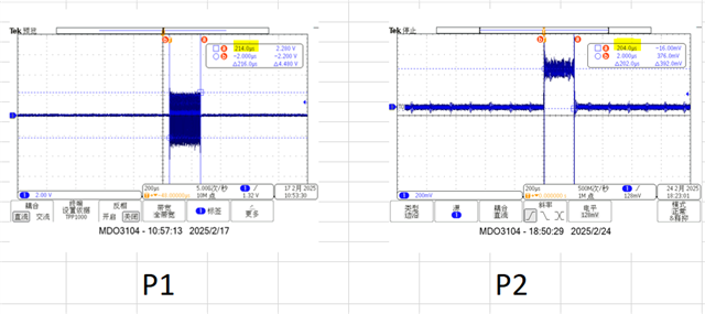
Here I update the test waveforms with current probe and differential probe.
Thanks
Lillian
Hi Jonathan,
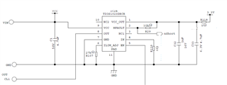
Refer to this part of the circuit, the 0Ω resistor of R110 is not connected, EN pin is connected to high level, so that OUT is in the output stage,
For short circuit test, add a small load resistor between VIN and OUT pins, and use a sliding rheostat.
Note: In actual test, no matter what voltage value VIN voltage is at, or whether it is NPN or PNP mode, the phenomenon mentioned above will be observed

Thanks
Lillian
Hi Lillian,
Thanks for the additional information and clarification about the scope probes.
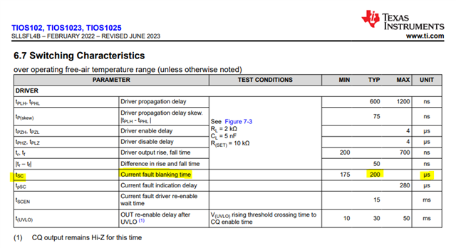
The TIOS102x has a current fault blanking time of approximately 200uS before it will disable the OUT pin driver. During this time the device will only have the current limit detection and feedback loop to try to adjust and limit the current flowing through the driver. Because this is a feedback loop, it is possible to have some complex loading from the inductance of the wires, resistance, and capacitance on the line that may setup some phase differences that result in oscillations.
I will try to replicate the results with a load resistance in the reported range.
Regards,
Jonathan
Hi Lillian,
I have been unable to recreate the same phenomenon being reported by the customer using a TIOx1x2xEVM and various load resistances between 1-100 ohms and a differential voltage scope capture across the resistance to calculate the current and monitor for oscillations.
I'm using 10-ohm 1%, 1W through hole resistors in parallel and series configurations on a bread board connected between the VCC supply and the OUT pins with test leads. The scope's differential +/- inputs are clipped to the leads of the resistors. I've tuned the ILIM_ADJ potentiometer on the board to 27kohms, so the setup should be equivalent to the customer's diagram.
I turned on the infinite persistence plot on the scope and allowed measurement to run for over 5k scope captures. For all load resistance values I saw proper current clamping and fault detection and auto recovery behavior. I did not see a difference based on a load resistance between 1-50 ohms.
I've added the scope plots to a tab in this spreadsheet. 0486.TIOS1023 question with TI Updates.xlsx
I'm wondering if there is some sort of inductance being introduced by the "sliding rheostat" they are using to create the load resistance.
Has the customer tried with a standard fixed resistor instead of a sliding rheostat?
Regards,
Jonathan
Hi Jonathan,
I'm also following this case, after try different kinds load such as: Slide Resistor, Cement Resistor, 1206 SMD Resistor,the result shows the output current is wrong when using Slide Resistor and Cement Resistor, right when using 1206 SMD Resistor. So we think that the test results are related to the type of load and output will oscillates when using inductive load. Is it possible? Do you have any idea about how to test the short-circuit protection when the load is inductive.
Thanks so much for your support!
Best Regards,
Yahui
Hi Yahui,
The current monitoring feature is a feedback loop and therefore can be susceptible to oscillations created by complex (RLC) load conditions. It sounds like you have confirmed that inductance of the slide and cement resistors are likely the cause of the observed results.
Can you try to add some capacitance to help filter and stabilize the feedback loop by altering the phase shift and frequency response?
Regards,
Jonathan
Hi Jonathan,
Will the TIOS1023 be damaged if it was short-circuited when driven an inductive load, and will the internal protection function likely to fail in this situation? Customers would like to know if you have short circuit protection test verification for inductive loads.Yes, they tried to measure the load current with a multimeter under short-circuit and output oscillation, actually the value is acceptable, so we think that theoretically it will not cause any damage to the chip. But we are not very sure about it. So it would be appreciated if you could provide some professional insights to eliminate the customer's concern about this question.
Best Regards,
Yahui
Hi Yahui,
In theory I also don't think this is a problem that would cause damage to the chip and the waveforms from the customer do not show excessive current. The device itself is capable of at least an amp of current through the bond wires and what I see in the waveforms appears to be a current level fluctuating between the regulated limits with the device's current loop changing between a heavy regulated to lightly regulated levels as a result of the phase delay.
In both the P1 a P2 waveforms provided, the duration is only about 200uS which is equal to the Current Fault Blanking Time when the driver is completely disabled as a result of the overcurrent condition. This is still functioning correctly and is the primary safety factor in the result of a short circuit event.


Because the fault detection is still working properly, I would say this should be comfort that there is low risk to the device becoming damaged under these conditions.
Regards,
Jonathan