This thread has been locked.

If you have a related question, please click the "Ask a related question" button in the top right corner. The newly created question will be automatically linked to this question.

DS90UB954-Q1: DS90UB953/DS90UB954 I2C Back Channel Communication Issue

Part Number: DS90UB954-Q1

Tool/software:

Dear TI Team,

I have designed a custom board using the DS90UB954TRGZRQ1 deserializer and DS90UB953TRHBRQ1 serializer. We are troubleshooting an issue where the I2C back channel communication is not working.

1. Setup & Configuration:

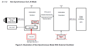
  • Deserializer (DS90UB954) and Serializer (DS90UB953) connected via coax cable
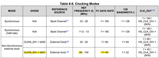
  • Non-synchronous mode configuration
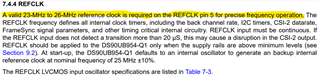
  • 50MHz external clock provided to serializer
  • Deserializer has no external clock

Hardware Configuration:

Deserializer (DS90UB954)

  • Mode Config: Pulled down (10KΩ)
  • IDX Pin: Pulled down (10KΩ)
  • PDB (Power Down) Config: Pulled up (10KΩ) with a 10µF bypass capacitor
  • i2c pull up 2.2k

Serializer (DS90UB953)

  • Mode Config: 75KΩ pull-up, 35.7KΩ pull-down
  • IDX Pin: 40.2KΩ pull-down
  • PDB Config: 10KΩ pull-up with 10µF bypass capacitor
  • I2C Pull-ups: 2.2KΩ

2. Observations & Steps Taken:

  1. Powered on the setup, but observed no LOCK established on the deserializer.
  2. Manually configured serializer register:
    i2cset -y 3 0x18 0x05 0x13 b
    After this, the deserializer LOCKED.
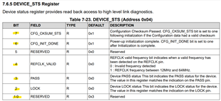
  3. Read deserializer register 0x04:  Received 0xCF 
  4. Configured deserializer I2C registers:
    i2cset -y 3 0x30 0x4c 0x1 b
    i2cset -y -f 3 0x30 0x6d 0x7c b
    i2cset -y 3 0x30 0x58 0x7a b
    i2cset -y 3 0x30 0x5c 0x31 b
  5. Tried to read back a register on the serializer:
    i2cget -y 3 0x18 0x1
    No response received.

3. Issues Faced:

  • Deserializer does not lock initially until I manually write to the serializer register.
  • Unable to read serializer registers over the back channel.
  • Status register 0x04 on deserializer reads 0xCF 

4. Questions:

  1. Is there a necessary initialization sequence for proper link and I2C back channel communication?
  2. Why is the deserializer not locking initially until I manually configure the serializer?
  3. Is my I2C configuration sequence correct?
  4. Any recommended debug steps to check back channel I2C functionality?

Any guidance would be highly appreciated.

Thank you!

  • Hello Puneeth,

    Deserializer has no external clock

    The deserializer requires an external clock for normal operation. Can you feed an external 25MHz clock to the deserializer?

    Best,

    Justin Phan

  • Dear Justin,

    Thank you for your response.

    As per the DS90UB954 datasheet, in non-synchronous mode, an external clock at the deserializer end is not required. However, I want to confirm whether:

    1. The 50MHz external clock provided to the serializer (DS90UB953) is sufficient to establish a stable link?
    2. Is the deserializer (DS90UB954) expected to automatically recover the clock from the FPD-Link III stream in non-synchronous mode?
    3. Can you clarify if an external 25MHz clock is still necessary at the deserializer end in non-synchronous mode?

    I would appreciate further clarification on this.

    Best regards

    puneeth

  • Hello Puneeth,

    The 954 deserializer MUST have a 25MHz clock fed into its XIN/REFCLK pin. Below is an excerpt from the DS90UB954 datasheet on ti.com.

    I don't recognize the Figure that you shared, but the latest version of the dataasheet states that the 954 device MUST use a 25MHz oscillator. The SER/DES devices will not be able to operate properly unless you apply this 25MHz clock to the deserializer.

    Best,

    Justin Phan

  • Dear Justin,

    Thank you for your clarification. Based on your suggestion, I have now connected a 25MHz external clock to the deserializer (DS90UB954), but I am still facing the same issue:

    • The deserializer does not lock until I manually modify the PLL register on the serializer.
    • After powering up, I observed that the serializer does not seem to initialize correctly until I write to the PLL-related registers manually.
    • Here are the register checks I performed:
      • Deserializer Register 0x04: Shows 0xdf (which indicates an issue).
      • After manually configuring the PLL on the serializer, the deserializer immediately locks.

    Could you please help clarify:

    1. Why does the deserializer fail to lock initially, even with the 25MHz external clock applied?
    2. Are there any recommended default register settings that must be configured on the serializer before power-up?
    3. Is there any dependency on the startup sequence that might cause this issue?

    aukclsr:/system/bin # i2cset -y 3 0x18 0x05 0x23 b //serializer pll clock configured
    i2cset -y 3 0x18 0x05 0x23 b

    aukclsr:/system/bin # i2cget -y 3 0x30 0x4   // deserializer status check
    i2cget -y 3 0x30 0x4
    0xdf
    aukclsr:/system/bin # i2cset -y 3 0x30 0x4c 0x1 b  // Rx port0 write enable
    i2cset -y 3 0x30 0x4c 0x1 b
    aukclsr:/system/bin # i2cset -y -f 3 0x30 0x6d 0x7c b //coax mode select
    i2cset -y -f 3 0x30 0x6d 0x7c b
    aukclsr:/system/bin # i2cset -y 3 0x30 0x58 0x7a b // i2c pass through enable
    i2cset -y 3 0x30 0x58 0x7a b
    aukclsr:/system/bin # i2cset -y 3 0x30 0x5c 0x31 b // serializer alias id
    i2cset -y 3 0x30 0x5c 0x31 b
    aukclsr:/system/bin # i2cget -y 3 0x18 0x1  // read serializer ID
    i2cget -y 3 0x18 0x1
    i2cget: i2c_read_byte: Transport endpoint is not connected

    I have followed the 953/954 basic design document, where it states that in non-sync mode, an external clock on the deserializer should not be required. Could you confirm if there are additional settings required to operate in this mode?

    Appreciate your guidance on resolving this issue.

    Best regards

    Puneeth

  • Hello Puneeth,

    Based on the MODE settings that you've shared, the 954/953 should be able to LOCK automatically at power-up.

    1. Are you able to provide the 954/953 schematics for your design, so that I can take a closer look?
    2. How are you feeding the 25MHz clock into the 954 REFCLK pin? Is the 25MHz signal low jitter and within the 954 datasheet specifications?
      1. If register 0x04 = 0xDF in the 954, then this indicates no issues. All the correct bits are set.
    3. What type of cable are you using and what length is it?
    4. In the serializer, since you are setting register 0x05 = 0x13, you are setting the CLKIN_DIV bit to 1. This means you are enabling a clock divider that is dividing the REFCLK by 2, which is reducing the Forward Channel rate from 4Gbps to 2Gbps.
      1. If you can only get LOCK when the FC rate is reduced, then this indicates that there is a violation in the IL/RL limit lines for the high-speed traces. Below are the requirements for the entire high-speed channel (PCB+Cable+PCB).
      2. Have you measured or simulated the IL/RL of your high-speed channel?
    5. After LOCK, if you cannot read any I2C registers in the remote serializer, then this also indicates excessive loss issues. I2C is a bidirectional control channel. If the high-speed channel has high loss in the lower or upper frequency ranges, then I2C bits may be lost, which can cause failed I2C commands.
      1. Are you able to provide Insertion Loss or Return Loss data for either the entire high-speed channel or just the PCB?

    Best,

    Justin Phan

  • Dear Justin,

    Thank you for your detailed response. Here are my observations and follow-up questions based on your points:

    1. 25MHz REFCLK to Deserializer (DS90UB954)

      • We are feeding a 25MHz clock (SG-210STF25.000000MHZY) to the 954 REFCLK pin.
      • The clock meets the low jitter specifications mentioned in the datasheet.
    2. LOCK Behavior:

      • At power-up, the Deserializer (954) does not achieve LOCK automatically.
      • LOCK happens only after setting register 0x05 = 0x13 on the Serializer (953) or if we change  serializer clock from 50Mhz to 25Mhz
      • Register 0x04 after LOCK = DF
    3. Cable Details:

      • Cable Type: 095FJZFJZSH-012
      • Cable Length: 304.8 mm
    4. I can share you the schematic if you provide mail id
    5. We do not have access to a Network Analyzer for measuring return loss and insertion loss. Are there any alternative methods you recommend for diagnosing and solving this issue?
    6. I2C Back Channel Issue:

      • After achieving LOCK, I still cannot read registers from the remote Serializer (953).
      • Could this be directly related to excessive loss in high-speed traces, as you mentioned?
      • Would adjusting EQ settings or pre-emphasis help mitigate this issue?

    Best regards

    Puneeth MK

  • Hello Puneeth,

    1. Can you probe the MODE pin of the 953 and 954 devices in the PCB? And share what voltage is being read on both devices?
    2. Is the 953 and 954 boards all custom PCB? Or are any EVMs being used in the system?
    3. I2C is a bi-directional protocol. If you have stable FC established, but there are issues in the BC, then remote I2C commands may be lost. The suspicion is that there is some violation in the S-Parameters at the lower MHz range if I2C commands are not being sent.
    4. The cable is 0.3 meters. A very short cable can cause high Return Loss.
      1. There is not a way to confirm the IL/RL in the system, unless you use VNA equipment to measure S-Parameter. You can potentially reach out to the cable vendor to see if they can help provide more information.
      2. Are you able to test using a 1 meter or 2 meter DACAR302 cable?
    5. You can send me your schematics to my email, j-phan1@ti.com 

    Best,

    Justin Phan

  • Dear Justin,

    Thank you for your response. Here are my findings and follow-up questions:

    1. MODE Pin Voltage Readings:

      • Serializer (953) MODE pin voltage: 0.594V
      • Deserializer (954) MODE pin voltage: 0V
    2. Hardware Setup:

      • Both the 953 and 954 boards are custom PCBs; we are not using any EVMs.
    3. I2C Issue & S-Parameter Violation:

      • I understand that I2C back channel issues could be due to S-Parameter violations at lower MHz frequencies.
      • Since we do not have access to a VNA to measure IL/RL, I will check with our cable vendor to get more details on S-Parameters.
    1. Cable Testing:

      • Currently, we are using a 0.3m cable.
      • We will test with a 1m or 2m DACAR302 cable and report the results.
      • Does TI recommend any specific cable vendors for validated performance?
    2. Schematics:

      • I will send the schematics to your email shortly.

    Please let me know if there are any other parameters we should check.

    Best regards,
    Puneeth

  • Hello Puneeth,

    1. Okay, the voltages are at the expected voltages.
    2. Okay.
    3. Since you do not have access to VNA equipment, have you simulated the Insertion Loss and Return Loss on the high-speed DOUT+/RIN+ traces on either PCB? It is important to confirm that the PCB and cable are within the recommended IL/RL limits that TI has defined.
    4. We generally recommend LEONI DACAR302 cables as a standard automotive cable provider. But there are many cable providers you can use instead as well. Please perform the test with a longer cable, to see if there are any changes.
    5. I will take a look at the schematics and provide feedback shortly.

    Best,

    Justin Phan

  • okay Justin thank you

  • Hello Puneeth,

    The schematic files are cut-off and do not show the SER or DES chips at all. If you like, you can re-send the schematics with the connections to the ICs shown clearly.

    Best,

    Justin Phan