This thread has been locked.

If you have a related question, please click the "Ask a related question" button in the top right corner. The newly created question will be automatically linked to this question.

DS42BR400: Temperature and communication problem

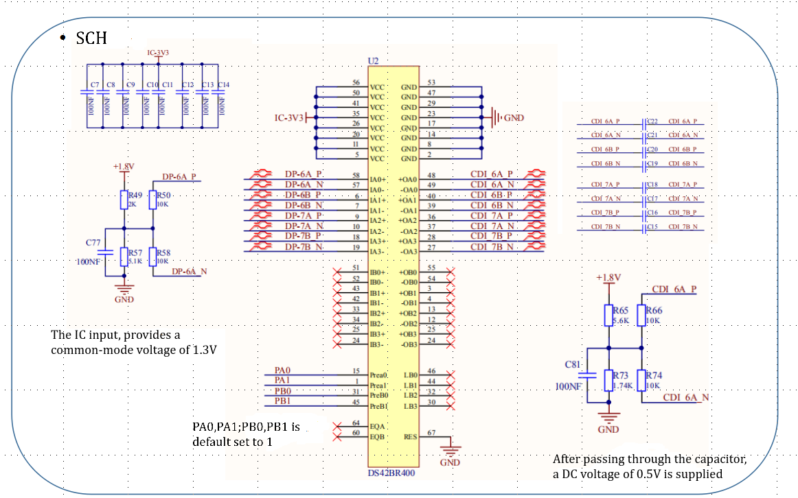
Part Number: DS42BR400
Other Parts Discussed in Thread: DS25BR400

Tool/software:

Hi E2E,

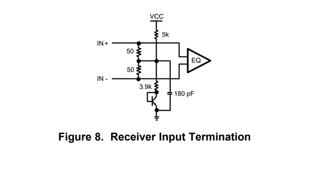
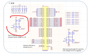
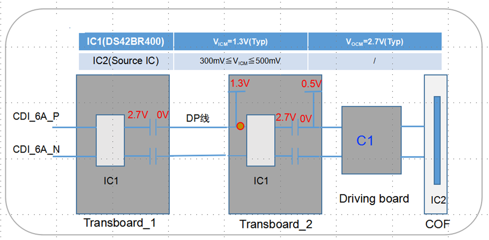
We are designing a screen display by using CML transceiver DS42BR400.

During the test, We found that the DS42BR400 surface temperature was to hot and the COF could not be locked.

Please help to solve the problem. 

Thanks

  • Hi,

    Looking at the schematic, the DS42BR400 CML input is internally biased, why do we have to external bias circuit? 

    Can you also please check the DS42BR400 pinout as it does not fully match with the pinout in the datasheet.

    Thanks

    David

  • Hi,

    The reason for the external bias circuit is that the DS42BR400's output VOCM does not meet the VICM requirements of IC2(COF).


    Can you help point out which pins are set incorrectly?

    Can you also please check the DS42BR400 pinout as it does not fully match with the pinout in the datasheet.

    BR

  • Hi,

    I am referring to the input, the input is internally biased as shown below, so you do not need the externally biasing circuit.

    This is a 60pin device, so I am not sure where pin 64 and pin 67 come from. I also do not see where the DAP is being connected. The DAP is the metal contact at the bottom side, located at the center of the WQFN-60 pin package. It should be connected to the GND plane with at least 4 via to lower the ground impedance and improve the thermal performance of the package.

    Thanks

    David

  • Hi David,

    1. Because the VICM of IC1 is 1.3V, an external bias circuit is added to the input end
    2. There are some errors in the schematic diagram, but the Layout should be correct. Please help to check it.

    Thanks

  • Hi,

    The high speed inputs are self-biased to about 1.3 V at IN+ and IN- and are designed for AC coupling. 

    If you removed the external bias network as shown below, can you see if it still works?

    Looking at the picture, I assume the DS25BR400 pad is connected to the PCB ground through the 5 GND via. Can you also make sure you have sufficient solder paste between the DS25BR400 pad and the PCB board ground?

    Thanks

    David

  • Hi,

    I will go ahead and close this E2E thread since there has been no activity. You can re-open this E2E thread by responding to it.

    Thanks

    David