This thread has been locked.

If you have a related question, please click the "Ask a related question" button in the top right corner. The newly created question will be automatically linked to this question.

TUSB1104: Guidance on Using Auto AEQ Mode in TUSB1104 for USB 3.2 Gen 2x2

Part Number: TUSB1104

Tool/software:

We have developed an FMC card utilizing the TI TUSB1104 redriver for testing our USB 3.2 Gen 2x2 (10 Gbps per lane) IP core. The host platforms for this testing include high-speed FPGA boards from Xilinx, Altera (Intel), Lattice Semiconductor, and Asmedia.

Our objective is to pass USB compliance testing.

Observations in Pin-Strap Mode (Default Settings):

  • Setup: Asmedia Type-C port + Amphenol cable
  • Lane 1: Fails to enumerate, remains in Recovery state during enumeration.
  • Lane 2: Successfully enumerates as USB 2.0, but does not achieve USB 3.2 operation.

Configuration & EQ Values Currently Used:

USB Connector Facing Port Receiver (CRX1, CRX2 pins) Equalization:

  • EQ Gain at 5 GHz minus Gain at 100 MHz = 11.6 dB

USB Host Facing Port Receiver (SSTX1, SSTX2 pins) Equalization:

  • EQ Gain at 5 GHz minus Gain at 100 MHz = 6 dB

Full Adaptive Equalization (Full AEQ) Mode Consideration:

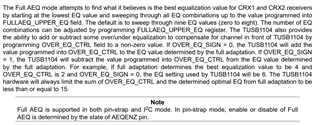
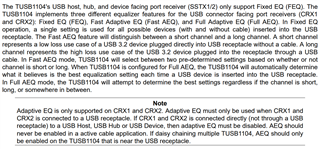
According to the TUSB1104 datasheet, when configured in Full Adaptive Equalization mode, the device autonomously determines the optimal equalization settings based on the signal channel characteristics. This mode dynamically adjusts the equalization for both short and long channels to optimize signal integrity.

We intend to use this mode for optimal performance.

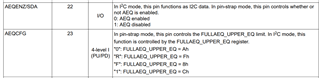
The AEQCFG pin is currently set to 0x08 (floating in pin-strap mode), which enables Full Adaptive Equalization mode.

Request for Guidance:

We would like detailed instructions on properly utilizing Full AEQ mode, including:

  1. Confirmation of correct AEQCFG settings for optimal performance.
  2. Application guidelines or reference documentation from TI regarding Full AEQ mode implementation.

  • Hi Sawan,

    The most important pins in AEQ mode are as follows. These will enable/disable AEQ and determine the max EQ that AEQ can go up to.

    The AEQ process is as follows:

    The time to achieve the best EQ setting will always be lower than 400us. If outside of this range there has been an issue in the setup and configuration of the device.  

    The AEQ will only apply to the connector facing pins. The host facing pins will have fixed EQ still, as this path will be set in the PCB. 

    Here is some more insight into AEQ from the datasheet:

    There is no optimal setting that will work across all boards. Redrivers must be tuned for each application they are used in. The key contributors are insertion loss and ISI. Each system will have different levels of these parameters. I recommend keeping the settings as follows. 

    SSEQ0/SSEQ1: this will be tuned based off of your PCB design. 

    AEQ: Enabled

    AEQCFG: set to max value (PUP)

  • Hello Vishesh,

    Thanks for your response.

    The time to achieve the best EQ setting will always be lower than 400us. If outside of this range, there has been an issue in the setup and configuration of the device.  

    - How to see this, I mean is there any register or something else to know that the EQ setting is outside the range?

  • Hi Sawan,

    This is defined in the image below. This is from the datasheet. If its longer than 400us, then there may be an issue as it exceeds the maximum time listed in the datasheet.