This thread has been locked.

If you have a related question, please click the "Ask a related question" button in the top right corner. The newly created question will be automatically linked to this question.

TDP0604: LV_DDC did not work after HPD_OUT assert

Part Number: TDP0604

Tool/software:

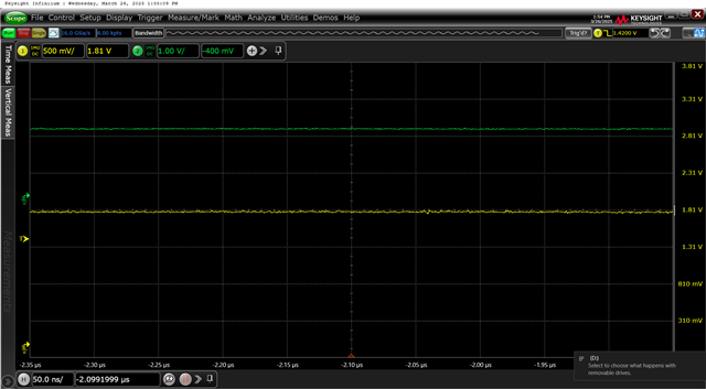
I have two projects using Apollo Lake + TDP0604 to output HDMI signals. However, in one of the projects, the DDC signals show no activity after the HPD# signal becomes active, and I only observe a 1.8V level.

I have tried disconnecting the connection to the PCH and confirmed that the PCH is properly polling the device.
Additionally, when I forcefully pull the LV_DDC low, the HV_DDC remains at a high level without any change.

Could an expert help analyze what other possible issues might be causing this situation and suggest a solution?
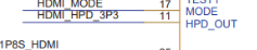
SCH :

"C:\Users\Shang\OneDrive - AAEON Technology\Share to external\pico-apl3_a11-20250124.pdf"
  • Hi Shang,


    Note that because VIO is 1.8V, HPD_OUT will output 1.8V, not 3.3V. Also, it is recommended to have external 220k pull down resistor for HPD_OUT. 

    If the source takes 3.3V HPD, HPD will not be detected. 

    LV_DDC are also supposed to operate from 1.8V so the voltage level seems accurate. 

    Additionally, when I forcefully pull the LV_DDC low, the HV_DDC remains at a high level without any change.

    Because of the buffer, pulling LV_DDC down should not affect HV_DDC. 

    Have you tried probing HV_DDC to see if there's any activities in HV_DDC?

    Best,
    J

  • I am indeed using 1.8V  with an added inverter; that net name was just a typo.

    When I change the level at LV_DDC, I expect to see the corresponding change at HV_DDC on the oscilloscope.

    What exactly do you mean by probing HV_DDC, and how should I perform it?

  • Hi,

    What exactly do you mean by probing HV_DDC, and how should I perform it?

    I apologize for the confusion. I misunderstood what you meant. 

    When I change the level at LV_DDC, I expect to see the corresponding change at HV_DDC on the oscilloscope.

    This is what I wanted to see. 

    the DDC signals show no activity after the HPD# signal becomes active, and I only observe a 1.8V level

    Do you mean that HPD# to the source goes high? If so, do you mean HPD_IN goes low?

    Note that DDC buffer is enabled when HPD_IN is high. So, when HPD# is high, HPD_IN would be low, then DDC buffer would be off. This could explain the behavior you are seeing. 

    Best,
    J

  • Hi Shang, 

    To update you on the progress:

    We have tested your board and seen the issue you mentioned. 
    We have tried to replicate the issue on our EVM but verified that the EVM works as expected. 
    We will put TDP0604 on your board into I2C mode to see if it is still having the issue. 
    We will keep you updated. 

    Best,


  • Hi Shang, 
    We are currently working to set TDP0604 on your board to I2C mode to directly interact with the device. 
    The solder jobs will be done tomorrow to verify the behavior under I2C mode. 
    We will keep you updated. 

    Best,
    J

  • Hi Shang, 

    To update you on the progress:

    We disconnected the LV DDC bus from the CPU and connected the bus to the I2C controller.
    We set our device into i2c mode also to directly interact with the device.
    We configured the registers 0x09 and 0x10.
    0x10 0x03 – Enables DDC buffer
    0x09 0x00 – Takes the device out of the PD state
    With this method, we can read the EDID information of the monitor through our device’s DDC buffer.

    We are reverting the board back into the pin-strap mode, and will attempt to get EDID information of the monitor from the LV DDC bus once the board is back.

    We will keep you updated.

    Best,
    J

  • Hi Shang, 

    We have validated that TDP0604 DDC buffer works as intended when the buffer is disconnected from the SoC.

    We disconnected the 0 ohm resistors of LV DDC bus that connects the SoC DDC bus with TDP0604.
    Then, we connected the LV side of DDC bus to Aardvark I2C Controller via level shifter to match the customer’s VIO setting of 1.8V.
    Using the aardvark I2C controller, we can read the EDID information of the monitor.
    Therefore, TDP0604 is functioning as intended. 

    Best, 
    J

  • Hi Shang, 

    We connected TDP0604 DDC buffer back to the SoC.
    Then, we put TDP0604 into I2C mode and tried the same setting we did when the buffer was disconnected from the SoC source. 
    We did not observe any I2C activity on the DDC buffer. 

    Below is the screenshot of the DDC buffer:


    Best,
    J