This thread has been locked.

If you have a related question, please click the "Ask a related question" button in the top right corner. The newly created question will be automatically linked to this question.

AM2632: Looking for the best method to verify the paths. Please review and provide feed back AM26C31 AM26C32C

Part Number: AM2632
Other Parts Discussed in Thread: AM26C31, AM26C32C, THVD1420, THVD1520

Tool/software:

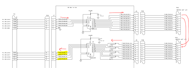
Can you provide me the normal response to the follow circuit if certain conditions occur.

1.  Jump the pins described in the table.
2.  Run the test. The test should fail.
3.  Keeping the first set of pins shorted, jump the second set of pins described in the table.
4.  Input a pulse train on  J7 1-4 identified in the table below.  
5.  Stop Pulse Train Open the pins described in the table, while keeping the other set shorted.
6.   Input a pulse train on  J7 1-4 identified in the table below.  The test should fail.
7.  Stop Pulse Train Open the pins described in the table. Both sets of pins should now be open.
8.   Input a pulse train on  J7 1-4 identified in the table below.  The test should fail.


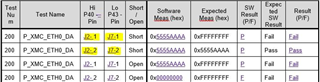
The pulse Train is 0XAAAA5555


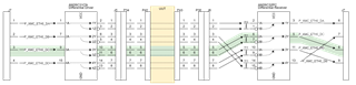
The intent here is to verify the signal paths…in and out. So, one of our team members thought that we would be able to use the method I sent to verify the path operates correctly. If there is a better methodology, please advise.

  • Hello Terrence,

    Can you please verify your device? What you've mentioned is not a device that I can see exists on TI.com so I am not sure where to route your question.

    If it is for AM2632 then need you to clarify the interface you are looking at.

    Best Regards,

    Ralph Jacobi

  • When using the part numbers AM26C31 AM26C32C  There was no forum in the drop down list for either part. They are quad driver and receiver 

  • Hello Terrence,

    I see, thanks for the info. I am not sure why they won't show up but this got routed to our Arm Microcontroller group, so very different family of devices. I will find the correct TI team to help with this and route your post accordingly. Please expect a short delay in reply for me to determine that and then for that team to respond. Thanks.

    Best Regards,

    Ralph Jacobi

  • Terrence,

    Do you have a schematic we can review of both the driver and receiver?

    It looks like (from your table), the measured value and expected values aren't matching. 

    I'm wondering if maybe the receiver is seeing noise or floating to an undefined level during the open cases. You may need to add an external fail safe circuit to ensure a proper bias on the receiver so the state is clearly defined since the receiver you are using doesn't include a fail safe bias (Vth is negative in fail safe protected transceivers).

    -Bobby

  • 1. When the Y/Z pins of the driver are connected to the A/B pins of the receiver, then the data goes through.

    2. When one or both of these connections are broken, then the output of the receiver is undefined. It might be high, or low (so you might not get the expected failure in the fourth entry of the table), or switch randomly.

    It is not clear what exactly you want to test. If you need to detect a broken connection, then use a pattern like AAAA5555.

  • Is there a replacement part with the built-in fail safe you can refer?

  • There is no four-channel device with fail-safe inputs.

    All modern transceivers (e.g., THVDxxx like THVD1520/THVD1420) have fail-safe inputs, but are 1+1 devices, so you would need four of them.

  • Clemens is correct, our 4x receivers are older devices and don't have the built in fail safe protection. The newer single channel transceivers are the ones that do have fail safe protection (you can verify this by looking at Vth+ and making sure its below GND). 

    To ensure a defined state, you will need to place external pull up (a pin) and pull down resistors (B pin) on differential receivers if you want to use the AM26 receivers. 

    -Bobby