This thread has been locked.

If you have a related question, please click the "Ask a related question" button in the top right corner. The newly created question will be automatically linked to this question.

TUSB1002: TX/RX Pinouts

Part Number: TUSB1002
Other Parts Discussed in Thread: , , HD3SS3220, HD3SS3212

Tool/software:

Hello,

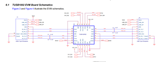
I'm working on a project on using the TUSB1002 to redrive a mux. Looking at the pinouts and reference schematics for it, I've been getting confused because it seems as if in all the schematics, the TX pin on one side is used to drive the TX pin on the other side instead of the RX pin. Like the eval board for example.


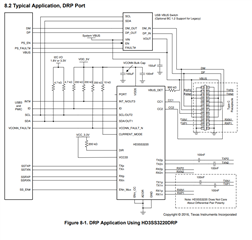
The block diagram for it doesn't help either since it shows that the RX pins are connected to the TX pins. In the image above, P2's TX_P and TX_N are connected to the TUSB1002 TX_P and TX_N which are outputs, meaning that an output is driving another output. I also checked with the USB-C plug side to see if the RX pins connect to the TX pins and that's not the case either. Could someone please explain why the TX and RX pins are connected to TX and RX rather than TX and RX being connected to RX and TX?

  • Hi Abraham,


    This schematic is for the TUSB1002A EVM, which uses a USB-A plug and a USB-A Receptacle. The reason the TX of the plug routes through the redriver to the TX of the receptacle is the the TX pins of the plug connect to the TX pins of a USB-A Port. Thus, these signals still need to be transmitted out through the type-A receptacle on the EVM. Additionally, since the plug side of the EVM will have the RX pins connect to the RX pins on whatever receptacle it is connected to, the USB-A receptacle on the EVM needs to route RX through to there.

    The TUSB1002EVM has a receptacle to receptacle implementation, where RX goes to TX and TX goes to RX. This is a more typical implementation, I believe.

    This block diagram just highlights the internals of the TUSB1002, and is meant to show how RX1 passes through to TX1. It does not necessarily mean that the RX pins can only be connected to RX lines and vice versa, but that the RX lines will receive a signal and then transmit it through the TX pins.

    Please let me know if you have any other questions!

    Thanks,

    Ryan

  • HI Ryan, 

    Thank you for replying.

    My apologies, I wasn't aware of the TUSB1200 and the TUSB1200A being separate, I'm using TUSB1002AIRGET for my project.

    In regards to the schematic for TUSB1002 EVM, I can see that the TX pins for the USB-B receptacle are connected to the USB-A's RX Pins, however the way they're routed still uses the TX pins on the redriver as inputs and the RX Pins as outputs. For example, when the USB-B Connector sends something on the transmit line, it'll go into TX1N/P and come out through RX1P/N which still doesn't make sense. Could you please explain a little more?

    From what you explained I still see something similar done in the reference schematics for the TUSB1002A, I have the following block diagram which is what I'm using for my project. Could you give it a look over?

  • HI Abraham,

    In regards to the schematic for TUSB1002 EVM, I can see that the TX pins for the USB-B receptacle are connected to the USB-A's RX Pins, however the way they're routed still uses the TX pins on the redriver as inputs and the RX Pins as outputs. For example, when the USB-B Connector sends something on the transmit line, it'll go into TX1N/P and come out through RX1P/N which still doesn't make sense. Could you please explain a little more?

    For the USB receptacles, the RX pins are receiving the signal from whatever cable is connected. That received signal moves through the RX lane until it reaches the redriver, where it is taken into the RX pins, processed, and then sent out through the TX pins of the redriver. After that, they are carried through through the lane to the TX pins of the opposite receptacle, as these signals are now going to be transmitted through TX.

    Its best to think of it as RX will always flow into TX. So on both lanes of the redriver, it will intake from the RX pins, as thats where the data is being received from, and then output through to the TX pins. When using receptacles, there should be no scenario where the signal with being transmitted through the RX pins of the receptacle.

    From what you explained I still see something similar done in the reference schematics for the TUSB1002A, I have the following block diagram which is what I'm using for my project. Could you give it a look over?

    Looking at this block diagram, while there is nothing stopping you from using the RX lanes with the TX pins, it is better to match TX with TX and RX with RX, just to avoid confusion. With TX for example, the microcontroller should be transmitting the signal, sending it through the redriver, and then using the TX pins of the HD3SS3220 to connect to the TX pins of the receptacle.

    Hopefully that helps, again, let me know if you have any other questions!

    Thanks,

    Ryan

  • the microcontroller should be transmitting the signal, sending it through the redriver, and then using the TX pins of the HD3SS3220 to connect to the TX pins of the receptacle.

    I'm sorry but this is getting me more confused. Typically you'd always have an RX going into a TX and a TX going into an RX, so if the microcontroller transmits through the TX pin of the HD3SS3220 and into the TX pin of the Receptacle, wouldn't that skew the data? Or are there different rules with USB 3.1?

    For the USB receptacles, the RX pins are receiving the signal from whatever cable is connected. That received signal moves through the RX lane until it reaches the redriver, where it is taken into the RX pins, processed, and then sent out through the TX pins of the redriver. After that, they are carried through through the lane to the TX pins of the opposite receptacle, as these signals are now going to be transmitted through TX.

    The same applies here, TX (output) is receiving output from RX (input).

  • Hi Abraham,

    Typically you'd always have an RX going into a TX and a TX going into an RX, so if the microcontroller transmits through the TX pin of the HD3SS3220 and into the TX pin of the Receptacle, wouldn't that skew the data? Or are there different rules with USB 3.1?

    Because the HD3SS3220 is just a mux, you can orient it with the TX lanes either through TX or RX. To me, it just makes sense that the TX lane/data goes through the TX lane of the mux to the TX pins of the receptacle, but its up to you really. But either way, the TX/output lanes from the microcontroller should be connected to the TX pins of the type-c receptacle (A2/A3, B2/B3), as the TX pins will transmit/output the signal from the microcontroller. The HD3SS3220 application below is an example of TX/RX routing with the HD3SS3220:

    Please let me know if you have any other questions.

    Thanks,

    Ryan

  • I understand the mux now, thank you.

    However I'm still confused as to why the TX pin on the microcontroller is driving the TX pin on the Receptacle, wouldn't the USB-C receptacle also be sending out signals from whatever device it's connected to on the TX pin which will collide with the microcontroller's TX Pin?

  • Hi Abraham,

    Whatever device is communicating with the microcontroller on the other end of the type-C cable will been connecting its TX lines to the TX pin of the connector on the device side. However, the cables are routed so that the TX pins on one end of the cable are the RX pins on the other end of the cable, ensuring that signals don't collide or try to send data on the same data lane. Thus, even if the devices on both sides of the cable transmit through the TX pin at the connector, their signal will appear on the RX pin on the opposite side.

    Please let me know if you have any other questions.

    Thanks,

    Ryan

  • Ok, now I'm understanding. Thank you.

    So for my project referring back to my block diagram, there shouldn't be an issue. The TX Pins on my receptacle can go through the Mux (RX or TX) and into the Redriver (Rx in and TX out) and into the RX pins on the microcontroller. Right?

  • Hi Abraham,

    The TX pins on your receptacle is sending data OUT of the receptacle, so you should have it connected to the data lane of the microcontroller which is outputting data, which I believe is the TX lane. And then the RX pins on the receptacle will be receiving data from the cable, so that should be attached to the lane of the microcontroller that is receiving data which I believe is the RX lane.

    Thanks,

    Ryan

  • Apologies, I'm still wrapping my head on the whole TX-TX and RX-RX routing.

    The target for my project is using sink devices, so the mux is in DFP, so if I connect the TX Pin from the microcontroller to the TX Pin of the receptacle, it'll end up at an RX Pin on the device it'll connect to. Right?

  • Hi Abraham,

    Yes, correct, you've got it right. For DFP with the HD3SS3220, you can follow this typical application: 

    Also, just as a heads up, for the HD3SS3220, please make sure you are using the ID pin to drive when VBUS is sent through the type-c receptacle (I.E When the ID pin is low, send VBUS to the type-C receptacle.) This is needed to ensure the CC pins complete CC negotiation correctly.

    Thanks,

    Ryan

  • For VBUS, I just have a direct connection to it, is having a switch there controlled by the ID pin critical? The HD3SS3220 also has it's CC pins connected to a USB PD controller, will this cause any issues?

  • Hi Abraham,

    For VBUS, I just have a direct connection to it, is having a switch there controlled by the ID pin critical? The HD3SS3220 also has it's CC pins connected to a USB PD controller, will this cause any issues?

    If you're using a PD controller, then I believe that should handle VBUS, yes.

    However, if you are using a PD controller, you don't necessarily need to use the HD3SS3220. You could use a different mux that doesn't have the CC controller functionality, like the HD3SS3212, and then use a pin from the PD controller to control the mux orientation via the SEL pin.

    The HD3SS3220 acts as a mux and a CC controller, but incorporating a PD controller makes that CC controller functionality unnecessary, as a PD controller performs the same functionality, as well as controlling VBUS.

    Thanks,

    Ryan

  • The PD controller I'm using does have a pin to do that however it must be configured through OTP I2C and we want to avoid having to do any initial programming for this project since it will slow the production/manufacturing time and will complicate the enclosure design for it. Does the HD3223212 actually do any PD negotiation? I believed the VBUS pin for it was strictly input as opposed to output, so I believe the only management it does using the CC pins is for data roles which I'm setting it for strictly DFP.

  • Hi Abraham,

    I'm not very familiar with PD controllers, but my understanding was that these could provide 5V in the place of VBUS. Additionally, it is my current understanding that typically PD controllers have some firmware that needs to be created and installed for proper functionality.

    The HD3SS3212 does not do any PD negotiation, however, there generally does need to be some way to limit VBUS from being sent until the CC negotiation is complete/says it needs to be sent. Constantly supplying VBUS to the port will cause issues during CC negotiation, which may affect the mux properly flipping based on the cable orientation.

    Additionally, we recommend against using the CC lines on both a CC controller and a PD controller on the same port. This will cause both the devices to try and communicate, which will cause errors during CC negotiation.

    Thanks,

    Ryan

  • The PD controller I'm using does require a PD contract to be established before sending out VBUS, and it does this using the CC Pins. So even though I have a direct connection to the VBUS pin on the HD3SS3220, Vbus does not get sent out until someone plugs in a USB-C cable. The CC pins between the 2 are still shared. I have sent my schematics to the manufacturer of the PD chip and they haven't found an issue with tying the CC pins together with the mux.

    Btw, I meant HD3SS3220 in my previous comment, not HD3SS3212, apologies.

  • Hi Abraham,

    Btw, I meant HD3SS3220 in my previous comment, not HD3SS3212, apologies.

    Got it, the HD3SS3220 does have some PD functionality in that it can advertise or detect different currents for power delivery. However, it does not perform any PD function outside of this. 

    The PD controller I'm using does require a PD contract to be established before sending out VBUS, and it does this using the CC Pins. So even though I have a direct connection to the VBUS pin on the HD3SS3220, Vbus does not get sent out until someone plugs in a USB-C cable. The CC pins between the 2 are still shared. I have sent my schematics to the manufacturer of the PD chip and they haven't found an issue with tying the CC pins together with the mux.

    I see, I think I was confused before. You don't have the VBUS always powered to the type-c connector, you just have it directly connected to the HD3SS3220, at least I think that's what I'm gathering. If you have VBUS controlled by the PD controller, and VBUS connected to the HD3SS3220 VBUS_DET pin correctly, then I don't think there's any issues. I will say that I'm a tad skeptical about having the CC pins connect to both the PD and CC controller, as this isn't something we typically recommend. If you want to leave it like this though you can, just if in the future you have issues with flipping the HD3SS3220, I would start by checking there with the DIR pin.

    Thanks,

    Ryan

  • The VBUS is directly connected to the HD3SS3220 and the VBUS pin. I was skeptical about having the CC pins tied together but I did have the manufacturer's FAEs take a look at my schematic and they say it looks good. If I do have any issues I'll be sure to check the DIR pin.

    Thank you so much Ryan for the help with everything, you have a good one.