Tool/software:
Hello Evan,
I opened a public thread for this one.
Since I am going to be on vacation for a while, I move the discussion to public and would let RD Ren-Fu to direct contact here.
Currently we have two requests now:
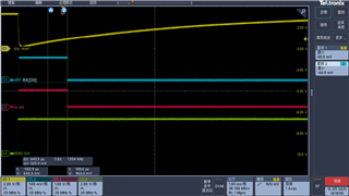
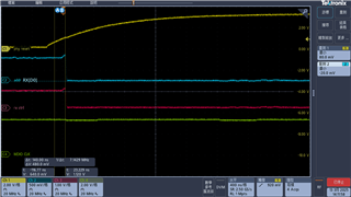
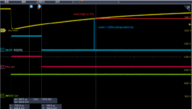
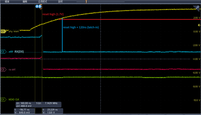
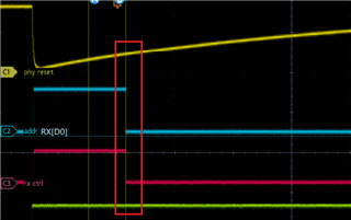
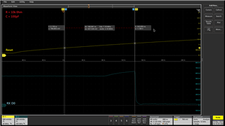
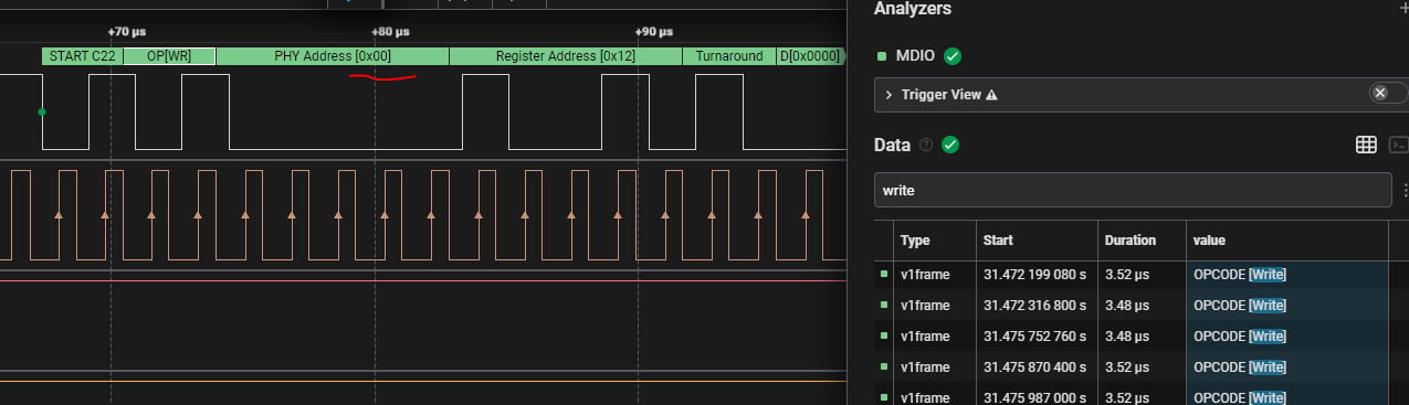
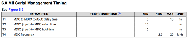
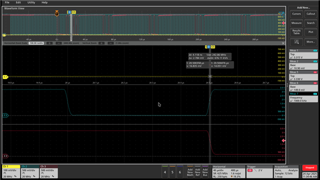
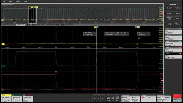
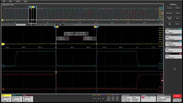
1. Did we get feedback checking the rising timing spec. with design team?
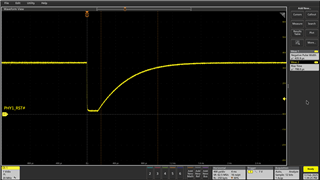
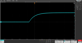
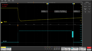
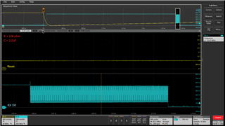
2. How is the testing result if we re-work the EVM to 0.1uF/1uF?
Also, for Ren-Fu, would you please help with two problems here:
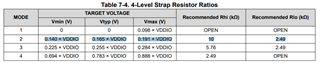
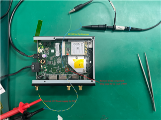
1. Do you have the scope for 0.1uF?
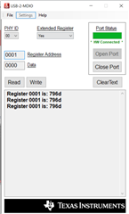
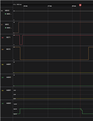
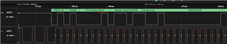
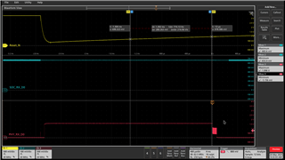
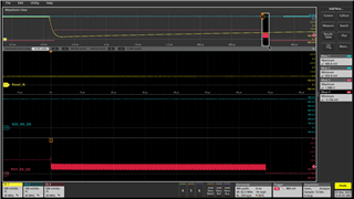
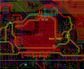
2.Could you also please share more details about the failure symptoms about reading PHY's register through MDIO, but the function of ethernet and LED is abnormal?
Is only link up failing, and is there any difference in register configuration when reading reg dump between pass/fail cases?
Thanks.
Let's have discussion over E2E here.
Matt's reply: