


Part Number: DS90UB960-Q1EVM
Other Parts Discussed in Thread: TSER953
Tool/software:
Hi Team,
we have DS90UB960-Q1EVM. I can able to run the link margin using analog launch pad. Attached test results.
Test case:
Deser: TDES960RTDT
Ser: TSER953
Cable length: 5meter
Result: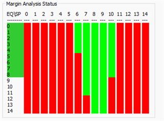
My query is
1.How to convert this report to eye diagram?
2.Can I run eye test?
3.What are all the test cases we can run to validate the PCB routing and cables with the help of EVM kit and the GUI?
4.How to validate and categorize pass and fail status of the test results?
kindly help us and share your inputs.
