This thread has been locked.

If you have a related question, please click the "Ask a related question" button in the top right corner. The newly created question will be automatically linked to this question.

DS90UB635-Q1: Channel Spec

Part Number: DS90UB635-Q1

Tool/software:

Hi team,

My customer Valeo are using DS90UB635 and DS90UB638 for their project, The operational condition are coax connection, POC solution(not including LED driving) used, 2Gbps, sync clock for serializer.

From their test results, S21 and S11 has different performance.

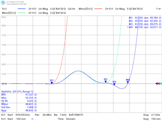
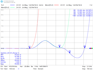
Below is the S parameter from serializer pin to deserialize pin:


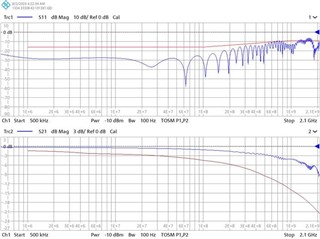
S21 has lots of margin, but S11 is not good, especially 600M~800MHz and 1.2G~1.8GHz.

What bad effects can "S21 OK, S21 NG" bring?

Could we accept this result "S21 OK, S21 NG" ? under what conditions?

Best Regards,

Xiaowei Zhang

  • Hello Xiaowei,

    Zoe will get back to you tomorrow with feedback

  • Hi Xiaowei, 

    Specifications for S21 and S11 must both be met. Are these the results for the system or the PCB by itself? Has the customer confirmed impedance matching throughout the trace to be 50 ohms? 

    Best,

    Zoe

  • Hi Zoe

    The test result is for the system: the whole link from SER pin to DESER pin, with all components mounted onto PCBA. What‘s the effect of the "S11 NG, S21 OK" case will bring to the link?

    Best Regards,

    Xiaowei Zhang

  • Hi Xiaowei,

    Total channel specifications must be met for the system in order to ensure proper operations of the devices. If violating one of the specifications, the system will be operating outside of the supported range. 

    Is it possible to collect the S22 measurement for this system? Does the customer have TDR measurements for the system? 

    Best,

    Zoe

  • Hi Zoe

    Both the S11 and S21 matter a lot for the whole link, respecting the channel spec.

    1. Valeo will try to measure S22 next time, but no requirement for S22 is found in channel spec. Does S22 have any affect to the link quality?

    2. about TDR, please check the waveforms and setup below:

    connect CAMERA(serializer) to VNA via SMA cable:

    connect ECU(deserializer)  to VNA via SMA cable:

    Best Regards,

    Xiaowei Zhang

  • Hi Xiaowei,

    The recommendation for S22 comes to identify if there is impedance discontinuity at one end of the cable in specific. 

    In the TDR measurements, the impedance exceed 55ohms on the camera and deserializer side at similar points. Is this identified to be the connector region? From a channel specification perspective this recommendations are for the PCB traces to be impedance matched to 50Ohm +/-10%.