Part Number: DP83869EVM
Other Parts Discussed in Thread: DP83869HM, DP83869,
Tool/software:
Hi,
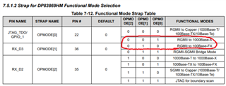
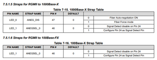
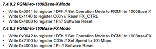
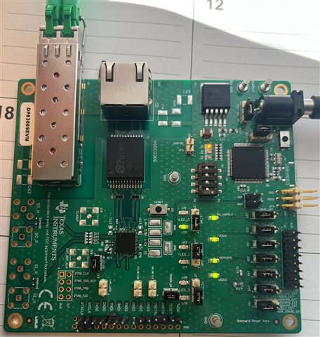
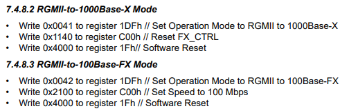
If I remove all the other parts and only use DP83869HM from the board with the SFP cage and RGMII. How should I configure the IC to run in fiber - RGMII mode?
Thank you