Part Number: DP83848K
Tool/software:
Hi,
My customer has a "Link" problem with DP83848K as below.
I would like you to support this issue.
1) Problem
In case of setting the PHYIC to 10M full duplex or 10M half duplex, and set the opposite side to 100M full duplex or 100M half duplex,
"Link-up" phenomenon has happened when plugging and unplugging the LAN cable in this connection.
2) Current PHYIC settings
Settings for 10M full-duplex: Set x"0100" to BMCR 0x00h
Settings for 10M half-duplex: Set x"0000" to BMCR 0x00h
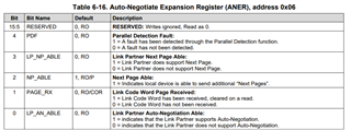
Check link status: See 0 bit of PHYSTS 0x10h
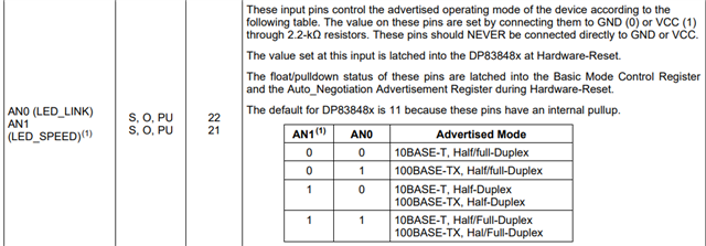
0x04h ANAR setting: 0x0181 (b"0000/0001/1000/0001")
3) Expected behavior
Since the communication modes on the PHYIC side and the opposite side are different, the customer expects a "Link-down" behavior.
4) Waveform confirmation results
When they checked the PHYIC output and input signal waveforms, the following was confirmed.
・The TD (+/-) pins output a 10Mbps First Link Pulse (FLP) waveform (as they set)
・The RD (+/-) pins input a 100Mbps waveform from the other side
I would appreciate your advice on what settings could be causing this issue and what measures can be taken.
If the register settings are incorrect, please let me know the correct settings.
I would particularly appreciate your advice on settings that could cause link malfunctions and the operation of the PHYIC.
Thank you for your support.
Best Regards,
Takumi