Hi,
We are currently designing with the TCA9617B and would like to clarify some points regarding Section 7.2.1.2 Detailed Design Procedure in the datasheet, specifically concerning pedestal overshoot. Could you kindly provide your insights on the following questions?
Question 1
If the input signal to the B-side is a clock with a 50% duty cycle, I believe that an increase in pedestal overshoot could distort the duty cycle of the output waveform from the A-side. Is this understanding correct?
Question 2
To prevent pedestal overshoot from occurring, how much should the input signal to the B-side be rounded?
Alternatively, are there any other methods to prevent pedestal overshoot?
Question 3
Does pedestal overshoot pose a problem for the TCA9617B in normal operation?
Question 4
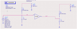
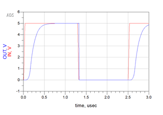
Is it possible to perform a signal integrity simulation of the TCA9617B using TINA-TI? Can pedestal overshoot be reproduced?
If so, could you provide some reference data?
Question 5
Is it possible to perform a signal integrity simulation using the IBIS model of the TCA9617B with an SI simulator other than TINA-TI?
Can pedestal overshoot be reproduced in such a simulation?
Thanks,
Conor