This thread has been locked.

If you have a related question, please click the "Ask a related question" button in the top right corner. The newly created question will be automatically linked to this question.

DS90UB954-Q1: Eye diagram for forward channel

Part Number: DS90UB954-Q1

Tool/software:

Hi TI Folks,

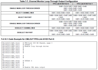
I want to test FPD signal forward channel quality for that i followed DS90UB954 datasheet I2C code  to route Video feed to CML OUT path written below

<aardvark>

<configure i2c="1" spi="0" gpio="0" tpower="1" pullups="1"/>

<i2c_bitrate khz="100"/>

<sleep ms ="100"/>

<i2c_write addr="0x30" count="3" radix="16">0xb0 00 14</i2c_write>

<sleep ms ="100"/>

<i2c_write addr="0x30" count="3" radix="16">0xb1 00 00</i2c_write>

<sleep ms ="100"/>

<i2c_write addr="0x30" count="3" radix="16">0xb2 00 80</i2c_write>

<sleep ms ="100"/>

<i2c_write addr="0x30" count="3" radix="16">0xb1 00 03</i2c_write>

<sleep ms ="100"/>

<i2c_write addr="0x30" count="3" radix="16">0xb2 00 28</i2c_write>

<sleep ms ="100"/>

<i2c_write addr="0x30" count="3" radix="16">0xb1 00 04</i2c_write>

<sleep ms ="100"/>

<i2c_write addr="0x30" count="3" radix="16">0xb2 00 28</i2c_write>

<sleep ms ="100"/>

<i2c_write addr="0x30" count="3" radix="16">0xb1 00 02</i2c_write>

<sleep ms ="100"/>

<i2c_write addr="0x30" count="3" radix="16">0xb2 00 A0</i2c_write>

<sleep ms ="100"/>

<i2c_write addr="0x30" count="3" radix="16">0xb0 00 08</i2c_write>

<sleep ms ="100"/>

<i2c_write addr="0x30" count="3" radix="16">0xb1 00 0F</i2c_write>

<sleep ms ="100"/>

<i2c_write addr="0x30" count="3" radix="16">0xb2 00 01</i2c_write>

<sleep ms ="100"/>

<i2c_write addr="0x30" count="3" radix="16">0xb1 00 10</i2c_write>

<sleep ms ="100"/>

<i2c_write addr="0x30" count="3" radix="16">0xb2 00 02</i2c_write>

<sleep ms ="100"/>

</aardvark>

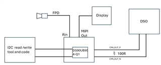
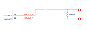
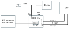
But i did not get the desire result as i dumped this code in my deserializer as a result the display tuned off but i am not getting signal at CMLOUT_P and CMLOUT_N on DSO i have attached one connection diagram kindly let us know what else should we do to get the signal on DSO.

  • Hello,

    Thanks for reaching out, these register settings look correct for RX port 1. Is the serializer/camera module connected on RX port 0 or RX port 1? If port 1 is correct, first verify that there is a stable lock between the serializer and deserializer by reading register 0x4D on the 954 multiple times with a short delay between reads. If each read has bit 0 set, and bit 4 not set, then lock is stable. Are any capacitors placed on the CMLOUT connection? Is the DSO set up for single ended or differential probing?

  • Hi Darrah Merillat,

    I have tried code for both the ports RX PORT 0 and RX PORT 1 But Getting the same result. We are using RX PORT 0 and there is no capacitor at CMLOUT and we are using differential probe in DSO 

     <aardvark>
    <configure i2c="1" spi="0" gpio="0" tpower="1" pullups="1"/>
    <i2c_bitrate khz="100"/>
    <sleep ms ="100"/>
    <i2c_write addr="0x30" count="3" radix="16">0xb0  00 14</i2c_write>
    <sleep ms ="100"/>
    <i2c_write addr="0x30" count="3" radix="16">0xb1  00 00</i2c_write>
    <sleep ms ="100"/>
    <i2c_write addr="0x30" count="3" radix="16">0xb2  00 80</i2c_write>
    <sleep ms ="100"/>
    <i2c_write addr="0x30" count="3" radix="16">0xb1  00 03</i2c_write>
    <sleep ms ="100"/>
    <i2c_write addr="0x30" count="3" radix="16">0xb2  00 28</i2c_write>
    <sleep ms ="100"/>
    <i2c_write addr="0x30" count="3" radix="16">0xb1  00 04</i2c_write>
    <sleep ms ="100"/>
    <i2c_write addr="0x30" count="3" radix="16">0xb2  00 28</i2c_write>
    <sleep ms ="100"/>
    <i2c_write addr="0x30" count="3" radix="16">0xb1  00 02</i2c_write>
    <sleep ms ="100"/>
    <i2c_write addr="0x30" count="3" radix="16">0xb2  00 20</i2c_write>
    <sleep ms ="100"/>
    <i2c_write addr="0x30" count="3" radix="16">0xb0  00 04</i2c_write>
    <sleep ms ="100"/>
    <i2c_write addr="0x30" count="3" radix="16">0xb1  00 0F</i2c_write>
    <sleep ms ="100"/>
    <i2c_write addr="0x30" count="3" radix="16">0xb2  00 01</i2c_write>
    <sleep ms ="100"/>
    <i2c_write addr="0x30" count="3" radix="16">0xb1  00 10</i2c_write>
    <sleep ms ="100"/>
    <i2c_write addr="0x30" count="3" radix="16">0xb2  00 02</i2c_write>
    <sleep ms ="100"/>
    </aardvark>
     

  • Hello Ginni,

    Do you have AC-coupling capacitors (100nF) on each pin?

    Please make sure you have a 100 ohm termination between the pins as shown in the picture. Also, make sure you have data at the RX input port of the UB954, i.e. a connected camera with stable LOCK


  • Hi Jaradat,

    yes, we are using AC coupling capacitor on FPD link RX side and for now we are not using coupling capacitor on CMLOUT side as shown in diagram

    As we are using differential probe having 50 ohm impedance in DSO and having 100Ohm termination at CML on board please suggest if there is any other way to test .

  • Hi Ginni,

    Are you using differential or single ended Just to clarify, the 100-ohm external termination resistors are required only if your oscilloscope does not have a 100-ohm differential termination.

    Please make sure your DES is connected to a SER/Camera outputting a valid video data. And you are measuring the CMLOUT configured to the right RX port.

    We have tested CMLOUT on our EVM using the code in the datasheet and it is working. Not sure why it is not working for you!

    For more details, please refer to this E2E thread:

    https://e2e.ti.com/support/interface-group/interface/f/interface-forum/935218/ds90ub954-q1-may-we-know-if-customer-need-test-eye-diagram-what-equipment-customer-need-to-prepare/3455930?tisearch=e2e-sitesearch&keymatch=ds90ub9%252A%2520AND%2520cmlout%2520AND%2520100#3455930