This thread has been locked.

If you have a related question, please click the "Ask a related question" button in the top right corner. The newly created question will be automatically linked to this question.

PCA9518: I2C waveform abnormal for PCA9518

Part Number: PCA9518
Other Parts Discussed in Thread: TCA9406, TXS0102, TCA9416, TCA9517A, TCA9617B, TCA9517

Tool/software:

We have a design with very similar traces that are shown in the linked question. (https://e2e.ti.com/support/interface-group/interface/f/interface-forum/1211283/pca9518-smbus-waveform-abnormal-for-pca9518)
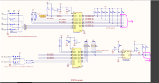
The issue was never fully addressed in that thread.   Our design does not use a rise time accelerator.  Apart from the ESP32 bus master, the devices are all slave devices and do not use clock stretching.  The scope traces below are based on 100kHz I2C transactions, although most zoom in on the rising edge where we are seeing the problems.  Our PCB has two separate I2C buses.  One uses a single PCA9518 hub, and the other uses two of them connected through the EXP pins as shown in the datasheet.  I have attached an excerpt of the schematic.


Both I2C trees are driven by an ESP32-S3 chip.  We have validated that the buses are being driven properly by disconnecting the hub chips and observing the I2C signals on an oscilloscope - rise time fall time, timing, sequence are all correct.

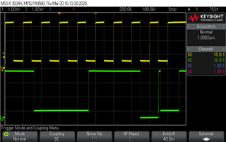
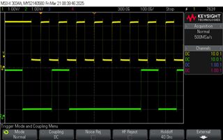
For the two hub circuit (left sheet above) this is what we see on the SCL0/SDA0 pins.

The spike in the rising edges resemble the problem shown in the inked question.  That thread suggests that a rise-time accelerator can cause this, but we do not have one in our design.

One thing we observe is that the spike is present even when no ENx are asserted, and it changes slightly depending on what ENx is asserted.


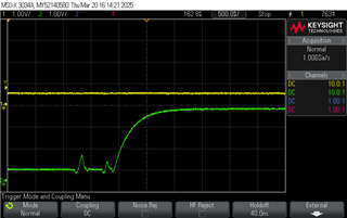
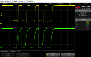
The spike is transmitted through the hub when it is enabled - here is SCL1 signal corresponding to the right image just above.

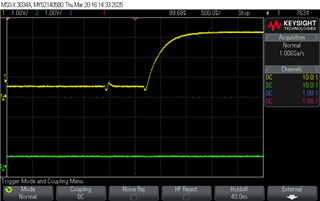
The single hub case has similar issues.  This shows the waveform at SCL0 when all ENx are asserted and it looks the same when all 4 ENx are deasserted.   This waveform corresponds with the datasheet, except for the tiny spike and relaxation at the initial rising edge.

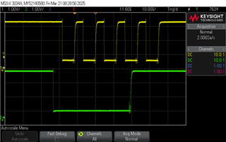
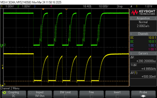
Here are SCL0 and SCL4 of the single hub bus when EN4 is asserted.  This time, the glitch did not pass through the device.


Are there any recommendations to fix this circuit?

  • Hi Ian,

    It looks like during the rising edge it overshoots the pedestal before coming back down and then eventually rising to a VCC. This might seem counter productive, but are you able to add external capacitance to the SCL0/SDA0 side? Can you attempt to add something like a 200pF load to attempt to rise slower and therefore smooth out this overshoot? 

    regards,

    Tyler

  • Thank you for the quick answer.  We have done a little testing with capacitors in various places, but I will attempt exactly this and report back.  Understanding the need to focus on the pedestal itself will help.  We were not considering this kind of SI issue because this is a very short trace on our PCB, and the signal is not being actively driven upwards.

  • Hi Ian,

    Understood. For this case and this type of buffer device with older buffer circuitry, the short traces might actually be working against the situation in terms of overshoot. 

    Lets see what additional capacitance does to the overshoots and if it smooths out the edge. I would say to adjust the PU resistance as well, but they are already very weak at 10k. 

    Regards,

    Tyler

  • You said: "For this case and this type of buffer device with older buffer circuitry, the short tr...."
    Older buffer circuitry - have we overlooked a newer pin compatible replacement?

    Ian

  • We have done the test with extra capacitance.  It helps somewhat, but the problem is not solved.  We tried various combinations.  (47pF,10kΩ), (390pF, 2kΩ), (390pF, 1.1kΩ), (220pF, 4.7Ω).  Results are better but about the same with the 220pF and 390pF caps.  With those, we were able to run bus with few errors at 10kHz rather than 100kHz.   This is with everything enabled but port 2 on the secondary hub.  Enabling it makes things worse, but we think this is a problem for the future since we don't need it enabled at the moment.

    Here is 390pF, 4.7kΩ, SCL1

    Looks great zoomed out, but this it at 10kHz.  It does not work at 100kHz, despite the edges having the same rates.

    zooming in shows these tiny spikes, worse on data than on clock.

    Here is 4.7kΩ. 220pF, 100kHz, SCL0/SDA0

    A runt transaction, I suspect caused by noise on one of the edges clocking extra bits to the receiving end.  We believe the SCL/SDA master is working because at 10kHz the results appear more sensible - see below.

    At 4.7kΩ. 220pF, 10kHz, SCL010kHz, sensible results most of the time.

    The same tiny spikes as above when we zoom in on edges, so 220pF vs 390pF on SCL0 doesn't change things much. (No picture)

    One thing I keep noticing is that the SCL0 signal never gets to 0V.  I would expect it can unless the hub is somehow fighting the bus master chip.  As you mentioned, there is light resistive loading on the bus - and not anywhere close to 3mA.

  • Here is 100kHz, 220pF, 4.7kΩ.  Green = SCL0, yellow = SCL3.

    The SCL0 bus is near to fully loaded with respect to rise time, but the glitch is still horrendous. It looks like a driver started to pull down the signal, then gave up.  The pulldown is to 0.5V which is a strong indication it is the hub doing the pulling down rather than the processor.

  • Hi Ian,

    Is it possible to add the capacitive loading to all channels of the device? 

    ~200pF to SCL0/SDA0 - SCL4/SDA4? 

    What other devices do the bus lines connect to? 

    Regards.

    Tyler

  • Hi Tyler,

    We were considering the same thing.  We will try that today.

    For connections, the buses are very lightly loaded.  We were using the hub to help with design reconfiguration rather than mitigating a backplane load. 

    On the primary hub, each channel is attached to a single NXP PCAL6524.
    On the secondary hub, channel 1 is attached to a I2C UART SC16IS750, channel 2 is connected to an expansion connector through the levelshifter - we have not plugged in a PCB to that channel yet, but if we did there would be a single I2C 2kbit eeprom

  • Hi Ian,

    We were considering the same thing.  We will try that today.

    Looking forward to the results.

    For connections, the buses are very lightly loaded.  We were using the hub to help with design reconfiguration rather than mitigating a backplane load. 

    On the primary hub, each channel is attached to a single NXP PCAL6524.
    On the secondary hub, channel 1 is attached to a I2C UART SC16IS750, channel 2 is connected to an expansion connector through the levelshifter - we have not plugged in a PCB to that channel yet, but if we did there would be a single I2C 2kbit eeprom

    Thanks for the explanation. This gives a bigger picture to what the downstream busses are connected to. 

    I also wanted to rule out any edge rate acceleration circuitry like TXS0102 / TCA9406 / TCA9416, of which devices do not work well with the PCA9518. 

    Regards,

    Tyler

  • We added 220pF capacitor to both signals of all 6 downstream lanes that can be active in our design.  This image shows that the controller clock is still messy, and one of the downstream ports.  The downstream signal look the same on either the upstream or the downstream hub.  No improvement.

  • Hi Ian,

    It sounds like you tried everything that I can think of trying. I have seen in the past similar abnormal behavior from other customers (you could check other public e2e's on this device to see if you can reach a solution). In the past, I have helped one customer by changing the PU and bus cap, and they were able to get it to work for some cases by the adjustments.

    To answer your question about "old buffer circuitry" this part is on an older process node developed back in 2006. We have since released I2C buffers such as TCA9517A / TCA9517 / TCA9617B etc. that don't have this double edge issue on the rising edge, new process, faster, better voltage range, static offset on one side. 

    If you are looking for a p2p drop-in device, there are some competitor devices out on the market of which I have seen work in a similar use case.

    Regards,

    Tyler

  • Funnily enough, some of those p2p devices arrived in my building today.  It will be interesting to see if they make a difference.

    I will keep the other devices in mind for future designs, but for now I have to make this work.  Luckily not in production. 

    Thank you for your help.

  • Ian,

    For sure! Thanks for all of your questions and I hope you can arrive at a solution soon. 

    Regards,

    Tyler

  • For completeness sake, you should know that the p2p competitor device fixed the problem.  I won't put a part number here, but it is mentioned on other questions about this part.

    Thanks for all the help.