This thread has been locked.

If you have a related question, please click the "Ask a related question" button in the top right corner. The newly created question will be automatically linked to this question.

DS90UB948-Q1: Displayed picture crashes, if the window is maximised or moved over the edge

Part Number: DS90UB948-Q1
Other Parts Discussed in Thread: DS90UB947-Q1, , ALP, USB2ANY

Tool/software:

Hi, we have a problem with our actual prototype setup.

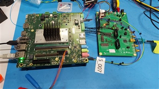
We are using a i.MX 8QuadXPlus with yocto as LVDS source for a DS90UB947-Q1. For the actual setup an eval-board is used for the i.MX8 and a DS90UB947-Q1EVAL as serializer.

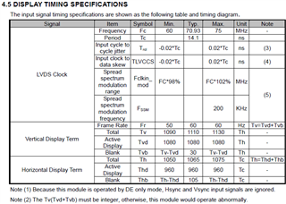
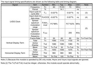
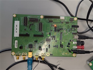
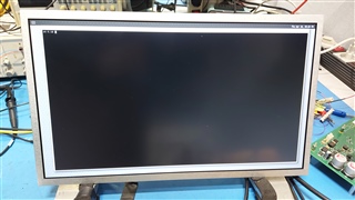
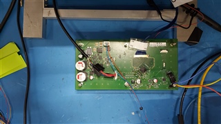
The deserializer (DS90UB948-Q1) is placed on our prototype-PCB which is connected to a display with a resolution of 1920x1080 points at 60Hz. The display is an InnoLux G156HCE-L01. The connection between display and PCB is realised with 20cm long micro-coax-wires.

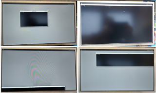
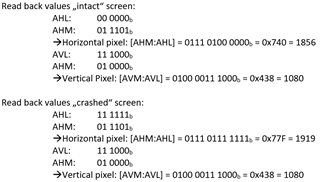
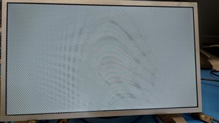
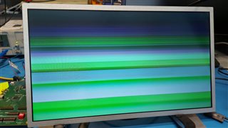
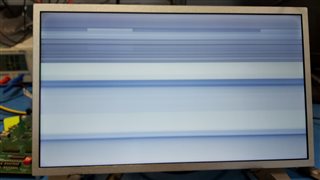
After the setup is powered up, we get the following picture:

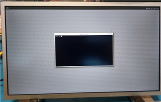
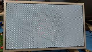
So far it seems all to be fine, but if this window is maximised or moved over the displayed window-borders, the following is displayed:

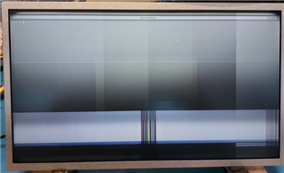
If the same display is connected directly to the eval-board of the i.MX8, the picture remains intact.

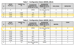
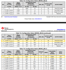
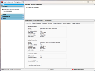
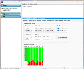
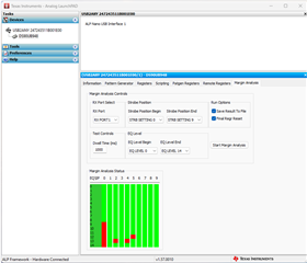
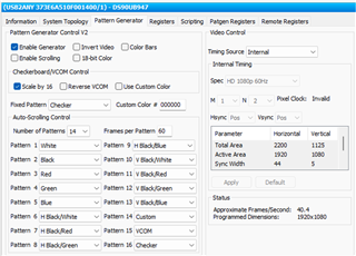
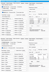
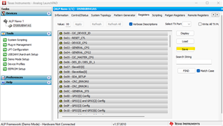
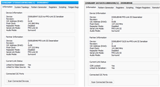
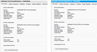
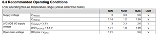
The registers of the serializer and the deserializer are set to the values shown in the excel-sheet.

DS90UB94x_RegisterSettings.xlsx

We tried a lot of things to solve the problem. Settings at the source in Yocto, replacing of cables and changing of the register settings from the serializer and deserializer. Nothing has soved the problem.

Can you give us a hint where we might be making a mistake or have a thought error?

Best regards

   Dirk Sievers

  • Hi Dirk,

    Apologies that it's been difficult.

    Have you tried doing 948 PATGEN and also 947 PATGEN before doing end-to-end video? Were these successful? 

    What is the PCLK for the display (Total horizontal pixels x Total vertical pixels x refresh rate)? Can you provide the full timings for the display?

    Based on the register configurations, It seems you are in FPD single-link mode, STP, and dual OLDI input with OLDI bit mapping for the 947, and dual OLDI output for the 948. Can you please confirm that this is what you intend to program for your system?

    947 Configurations

    948 Configurations

    Lastly, I want to confirm - any movement of the window will cause this exact glitch to occur? If you could provide a video of the glitch happening, that would help a lot. 

    BR,

    Esther

  • Hi Esther,

    thanks for your quick response.

    I have mainly provided technical support for the project so far and am not yet 100% familiar with the subject matter. My colleague is on vacation at the moment and I hope I'm getting everything right.

    My colleague used the PATGEN on both the 947 and the 948 to generate testimages on the display. This worked in both cases.

    The information for the display is shown in the following picture:

    According to this table, the total PCLK for the complete signal will be (2*1065) * 1110 * 60Hz = 141,858 MHz.

    The pictures you added are for the Mode Select Pins.

    The hard-wired settings for the 947 are:
          MODE_SEL0 = 1,008V (5) = OLDI_DUAL=1 & REPEATER=0
          MODE_SEL1 = 0,383V (2) = MAPSEL=0(OpenLDI) & COAX=0

    The hard-wired settings for the 948 are:
          MODE_SEL0 = 1,241V (4) = Dual OLDI output, MAP_SEL=1(OpenLDI) & OUTPUT_MODE= 00
          MODE_SEL1 = 0V (2) = REPEATER=0, MODE=00, HS_BackChannel=5Mbps & Input = STP

    At start-up of the Yocto-system some registers are set to new values. The configuration over the I2C-connection works well.

    We are using a dual link STP connection between 947 and 948 and it shall be detected automatically (standard-setting). The dual-OLDI input and output is the correct setting.

    Regarding the window-problem: Moving the window pn the screen works and it can be moved to each edge. The problem occurs, if the window is maximised or enlarged (see videos).

     Best Regards
        Dirk

  • Hi Dirk,

    Thanks for the information and video! If DES and SER PATGEN are both okay, then we can isolate the issue to the path between the SoC and the 947. Also, the mode straps are fine and the PCLK is in range, so we can rule out hardware. 

    Can you confirm that the video timings are being sent correctly by the SoC?

    At start-up of the Yocto-system some registers are set to new values

    Do you know if the configuration of these registers might interfere with the video stream? 

    BR,

    Esther

  • Hi Esther,

    today I have modified the test-setup and i have connected the display directly to the eval-board with the i.MX8. The displayed screen is OK and maximizing and resizing makes no problems.

    In the "Exploring the Test Pattern Generation Feature..." document (SNLA132G) is in chapter 4.5 a "Resolution Readback Example"described. I executed the example over I2C once with the "intact" screen and once with the "crashed" screen.

    Is seems, the resolution is not correctly reconstructed by the deserializer. The SoC generates a resolution of 1920*1080 pixel.

    What may be the reason for this condition? A config-problem or a signal-problem?

    Best Regards
        Dirk

  • Hi Dirk,

    Are you running a specific script for this configuration? Can you please provide this script?

    Do you have local I2C access to the 948? If you do, can you run MAP analysis on the 947-948? It could be a link integrity issue causing the incorrect resolution being reconstructed at the DES. Here is some information on how to set up MAP Analysis. 

    snlu243 (1).pdf

    BR,

    Esther

  • Hi Esther,

    here is the I2C communication at the start of the yocto system on the i.MX8.

     I2C_StartCommunication.xlsx

    First, the affected byte is read in and than the changed byte is written back.

    For the MAP-test I have to change the test-setup again.
    But this is a setup with two DS90UB94x eval boards. 

    Can I connect the I2C of our final hardware to the USB2ANY connector of the Eval-Board (only powerd over USB) for using the ALP tool?

    I will give a feedback, if I have a result.

  • Hi Dirk,

    here is the I2C communication at the start of the yocto system on the i.MX8.

    Did you program these commands based on any reference material or was it made from scratch? I've attached a sample 947 Init Code for your reference. 

    """
      TI Confidential - NDA Restrictions
    
      Copyright 2020 Texas Instruments Incorporated. All rights reserved.
    
      IMPORTANT: Your use of this Software is limited to those specific rights
      granted under the terms of a software license agreement between the user who
      downloaded the software, his/her employer (which must be your employer) and
      Texas Instruments Incorporated (the "License"). You may not use this Software
      unless you agree to abide by the terms of the License. The License limits your
      use, and you acknowledge, that the Software may not be modified, copied or
      distributed unless embedded on a Texas Instruments microcontroller which is
      integrated into your product. Other than for the foregoing purpose, you may
      not use, reproduce, copy, prepare derivative works of, modify, distribute,
      perform, display or sell this Software and/or its documentation for any
      purpose.
    
      YOU FURTHER ACKNOWLEDGE AND AGREE THAT THE SOFTWARE AND DOCUMENTATION ARE
      PROVIDED AS IS WITHOUT WARRANTY OF ANY KIND, EITHER EXPRESS OR IMPLIED,
      INCLUDING WITHOUT LIMITATION, ANY WARRANTY OF MERCHANTABILITY, TITLE,
      NON-INFRINGEMENT AND FITNESS FOR A PARTICULAR PURPOSE. IN NO EVENT SHALL TEXAS
      INSTRUMENTS OR ITS LICENSORS BE LIABLE OR OBLIGATED UNDER CONTRACT,
      NEGLIGENCE, STRICT LIABILITY, CONTRIBUTION, BREACH OF WARRANTY, OR OTHER LEGAL
      EQUITABLE THEORY ANY DIRECT OR INDIRECT DAMAGES OR EXPENSES INCLUDING BUT NOT
      LIMITED TO ANY INCIDENTAL, SPECIAL, INDIRECT, PUNITIVE OR CONSEQUENTIAL
      DAMAGES, LOST PROFITS OR LOST DATA, COST OF PROCUREMENT OF SUBSTITUTE GOODS,
      TECHNOLOGY, SERVICES, OR ANY CLAIMS BY THIRD PARTIES (INCLUDING BUT NOT
      LIMITED TO ANY DEFENSE THEREOF), OR OTHER SIMILAR COSTS.
    
      Should you have any questions regarding your right to use this Software,
      contact Texas Instruments Incorporated at www.TI.com.
    
    """
    ############################
    # DS90UB947-Q1 Init Code Example v1.1
    # 947->948, Dual FPD-Link STP, 1920x1080@60Hz
    ############################
    
    import time
    import sys
    
    # System dependant variables - adjust according to system 
    UB947 = 0x18        # 947 I2C Address
    UB948 = 0x68        # Remote 948 Address
    StartAmbTemp = 25   # Example temperature measured by local sensor on PCB (Ambient temp around 947). In real system this should be read back from temp sensor during initialization 
    Hres = 1920         # Expected horizontal active resolution
    Vres = 1080         # Expected vertical active resolution 
    
    def pollstate():
        count=0
        board.WriteI2C(UB947,0x23,0x80)
        board.WriteI2C(UB947,0x24,0x80)
        mask = int('11111',2)
        state = board.ReadI2C(UB947,0x24,1)
        while (state & mask) != 27:   #27 = 5'b11011
            time.sleep(0.01)  #10ms delay
            state = board.ReadI2C(UB947,0x24,1)
            count = count +1
            if count == 10:
                print "Error: Serializer is not in Normal state"
                return(1)
        
        board.WriteI2C(UB947,0x23,0x0)
        board.WriteI2C(UB947,0x24,0x0)


    def initsequence():
    
        board.WriteI2C(UB947,0x03,0xDA) # Set I2C passthrough
        
        linked = 0
        retry = 0
        mask = int('10000000',2)
        while linked == 0:
            STS = board.ReadI2C(UB947,0x5A,1)
            if ((STS & mask) != 0):
                linked = 1
                print "Deserializer Detected"
            else:
                time.sleep(0.1)
                retry = retry + 1
                if retry == 10:
                    print "Error: No Deserializer Detected"
                    return()
    
        board.WriteI2C(UB948,0x4A,0x01) # Disable OLDI outputs on 948 to prevent screen glitches from appearing during the init process 
    
        ##### Init A Sequence
    
        # Errata #5 and 6
        board.WriteI2C(UB947,0x5B,0x03) # Force dual FPD-Link, disable reset on PLL frequency change 
    
        # Errata #10
        board.WriteI2C(UB947,0x16,0x02) # Adjust BCC watchdog timer to minimum
    
        # Errata #11
        board.WriteI2C(UB947,0x04,0x90) # Prevent AVMUTE for non-HDCP systems


        state_error = pollstate()  # Poll 947 state machine prior to applying init B errata
    
        if state_error == 1:
            return()
    
        ##### Init B Sequence 
    
        # # Errata #2 (only for older non-eFuse devices)
        # board.WriteI2C(UB947,0x40,0x10)
        # board.WriteI2C(UB947,0x41,0x4A)
        # board.WriteI2C(UB947,0x42,0x3F)
        # board.WriteI2C(UB947,0x41,0x4B)
    
        # if StartAmbTemp < 10:
        #     board.WriteI2C(UB947,0x42,0x88)
        # else:
        #     board.WriteI2C(UB947,0x42,0x89)
        # board.WriteI2C(UB947,0x41,0x49)
        # board.WriteI2C(UB947,0x42,0x10)
        # board.WriteI2C(UB947,0x42,0x00)
        # board.WriteI2C(UB947,0x40,0x14)
        # board.WriteI2C(UB947,0x41,0x4A)
        # board.WriteI2C(UB947,0x42,0x3F)
        # board.WriteI2C(UB947,0x41,0x4B)
        # if StartAmbTemp < 10:
        #     board.WriteI2C(UB947,0x42,0x88)
        # else:
        #     board.WriteI2C(UB947,0x42,0x89)
        # board.WriteI2C(UB947,0x41,0x49)
        # board.WriteI2C(UB947,0x42,0x10)
        # board.WriteI2C(UB947,0x42,0x00)
    
        # Errata #3 
        board.WriteI2C(UB947,0x40,0x10)
        board.WriteI2C(UB947,0x41,0x49)
        board.WriteI2C(UB947,0x42,0x16)
        board.WriteI2C(UB947,0x41,0x47)
        board.WriteI2C(UB947,0x42,0x20)
        board.WriteI2C(UB947,0x42,0xA0)
        board.WriteI2C(UB947,0x42,0x20)
        board.WriteI2C(UB947,0x42,0x00)
        board.WriteI2C(UB947,0x41,0x49)
        board.WriteI2C(UB947,0x42,0x00)
    
        time.sleep(0.01)
    
        ##### Timing Confirmation 
    
        retry = 0
        Hconfirm = 0
        Vconfirm = 0
        while (retry < 3):
            board.WriteI2C(UB948,0x68,0x08) # Enable PATGEN BIST
            time.sleep(0.1) # Critical time delay - do not adjust to a shorter value 
            board.WriteI2C(UB948,0x68,0x19) # H active High monitor
            Hhigh = board.ReadI2C(UB948, 0x69, 1)
            board.WriteI2C(UB948,0x68,0x09) # H active Low monitor
            Hlow = board.ReadI2C(UB948, 0x69, 1)
            board.WriteI2C(UB948,0x68,0x39) # V active High monitor
            Vhigh = board.ReadI2C(UB948, 0x69, 1)
            board.WriteI2C(UB948,0x68,0x29) # V active Low monitor
            Vlow = board.ReadI2C(UB948, 0x69, 1)
            board.WriteI2C(UB948,0x68,0x00) # Disable PATGEN BIST
    
            mask = int('00111111',2)
    
            hlowmask = Hlow & mask
            hhighmask = Hhigh & mask
            vlowmask = Vlow & mask
            vhighmask = Vhigh & mask
    
    
            hhighmask = hhighmask << 6
            vhighmask = vhighmask << 6
    
            Hactive = hhighmask | hlowmask
            Vactive = vhighmask | vlowmask
    
            if Hactive != Hres:
                retry  = retry + 1
                board.WriteI2C(UB947,0x40,0x10) # Reset OLDI PLL
                board.WriteI2C(UB947,0x41,0x49)
                board.WriteI2C(UB947,0x42,0x16)
                board.WriteI2C(UB947,0x41,0x47)
                board.WriteI2C(UB947,0x42,0x20)
                board.WriteI2C(UB947,0x42,0xA0)
                board.WriteI2C(UB947,0x42,0x20)
                board.WriteI2C(UB947,0x42,0x00)
                board.WriteI2C(UB947,0x41,0x49)
                board.WriteI2C(UB947,0x42,0x00)
                time.sleep(0.1)
            else:
                Hconfirm = 1
            if Vactive != Vres:
                retry  = retry + 1
                board.WriteI2C(UB947,0x40,0x10) # Reset OLDI PLL
                board.WriteI2C(UB947,0x41,0x49)
                board.WriteI2C(UB947,0x42,0x16)
                board.WriteI2C(UB947,0x41,0x47)
                board.WriteI2C(UB947,0x42,0x20)
                board.WriteI2C(UB947,0x42,0xA0)
                board.WriteI2C(UB947,0x42,0x20)
                board.WriteI2C(UB947,0x42,0x00)
                board.WriteI2C(UB947,0x41,0x49)
                board.WriteI2C(UB947,0x42,0x00)
                time.sleep(0.1)
            else:
                Vconfirm = 1
            if (Hconfirm == 1) and (Vconfirm == 1):
                break
    
        if (retry > 2):
            print "Error: Timing confirmation failed. Double check expected video resolution and OLDI video input"  
            return()
        else:
            print "Initialization Complete"
            board.WriteI2C(UB948,0x01,0x01) # Digital reset to restart AEQ 
            time.sleep(0.1) # Allow time for 948 to relock 
            board.WriteI2C(UB948,0x4A,0x00) # Enable OLDI outputs on 948
    
    initsequence()

    I noticed in your script that you are overwriting the DES_ID, which would mess with the I2C communication between the SERDES. Is there a reason for this write? See below for comments. 

    5125.I2C_StartCommunication.xlsx

    But this is a setup with two DS90UB94x eval boards. 

    Do you mean you are using a DS90UB947 eval board to test with a 948 hardware system? Or are you saying you're seeing this screen problem using 947 and 948 eval board? 

    Can I connect the I2C of our final hardware to the USB2ANY connector of the Eval-Board (only powerd over USB) for using the ALP tool?

    Yes, that works. As long as the USB2ANY is connected to the I2C lines of the 948 hardware system, you can use ALP on your laptop to run MAP Analysis on the 948 profile. 

    BR,

    Esther

  • Hi Esther,

    for first tests, we started with i.MX8 eval board, serializer eval board, deserializer eval board and display.

    The discribed problem occured when we replaced the deserializer eval board with our hardware.

    The MAP Analysis is only on the 948 available und for a first MAP analysis try I can use the "old" setup for getting a reference measurement. As second step I use the USB2ANY connector for connecting our 948 hardware over i2c and then making a further test. (Before I start the test, I wanted to check my thesis, that I can use the 948 eval board in the described way...)

    BR
       Dirk

  • Hi Dirk,

    Before I start the test, I wanted to check my thesis, that I can use the 948 eval board in the described way...

    Yes, that works. Appreciate you checking in. 

    for first tests, we started with i.MX8 eval board, serializer eval board, deserializer eval board and display.

    Just to confirm, there were no abnormalities with the display when using the deserializer eval board?

    I noticed in your script that you are overwriting the DES_ID, which would mess with the I2C communication between the SERDES. Is there a reason for this write?

    Also, wanted to double check the reason you were overwriting the DES_ID in your script? 

    BR,

    Esther

  • Hi Esther,

    the question of the test setup with the deserializer evaluation board worked isn't quite so easy to answer.
    When I build up the test setup for my software colleague, after some initial hiccups, the whole thing worked reliably for months. An additional I2C-Touch was also connected to the deserializer.
    After the test-setup was moved to my colleagues working place, the test setup never worked reliably again...
    Actual we wanted to replace the 948 eval board with a new one, but unfortunately there aren't any available for purchase at the moment.

    My software colleague will remove the corresponding part from the script. He has also checked the script, you enclosed. The problem is that the serializer-deserializer connection esatblishes a connection relatively short after the power is turned on. When Yocto starts some time later on the i.MX8, he only applies the few settings specified in the script. This has actually worked well.

    Finally, here are the results of the MAP-Analysis:

    I think, this should not be the problem in this test setup.

  • Hi Dirk,

    When I build up the test setup for my software colleague, after some initial hiccups, the whole thing worked reliably for months. An additional I2C-Touch was also connected to the deserializer.

    Do you mean the setup with two eval boards worked reliably for months, or with the 947 eval board and the 948 hardware? Just want to get an idea of what could have happened during the time it got moved. 

    Actual we wanted to replace the 948 eval board with a new one, but unfortunately there aren't any available for purchase at the moment.

    Let me check internally to see if we can get a restock. 

    The MAP analysis looks fine, as long as you are using less than 10 EQ. 

    BR,

    Esther

  • Hi Esther,

    the test-setup, which works reliably for months was build with 947 eval board and 948 eval board. During theses months, we designed the PCBs and additionally we worked on another project. When our 948-PCB was to be put into operation, the test setup was moved. After this move, the test setup (947 & 948 eval boards) no longer worked correctly. Then my colleagues measured and tried everything possible, but without success. Since we didn't know what to do, we turned to the E2E forum.

    BR,
    Dirk

  • Hi Dirk,

    Were you able to test out the new 947 init script? It implements some erratas. 

    Can you bring up 947 PATGEN again using the ALP PATGEN tab with the SoC disconnected? If you can send a picture of the PATGEN setup and the display? 

    Since the signal integrity on the 948 board and evaluation board are both okay, it may implicate the 947.

    Lastly, if it's possible to get reg dumps of normal vs abnormal screen for both 947 and 948, that would be great. 

    BR,

    Esther

  • Hi Esther,

    here are some pictures using the 947 pattern generator:

    1) Using the pre-defined settings for a 1920*1080 60Hz display:
       
    The displayed pictures are OK and I could see no errors. Unfortunately these settings produce only 40.4 frames/second, not 60 frames/second.

    2) Using the settings from the display (G156HCE-L01):


    If the "Scale by 16" is unchecked, the picture shows this:

    and the bars are running... A white picture or a picture starting with white is also no good choice:

    Unfotunately, we could not integrate the startup script that easily. The serializer and deserializer settings are configured in the driver at some point. For implementing these scripts into the start-up process, my colleague has to modify the display driver, which is provided by Yocto.

    Is it possible to store a register dump with the ALP-environment? I will try to make some dumps tomorrow.

    BR,
        Dirk

  • Hi Dirk,

    Thanks for the pictures and explanation. Let's focus on getting the PATGEN working for the 947 and 948 evaluation boards. 

    Just to confirm, before you moved the setup, 947 PATGEN, 948 PATGEN, and end-to-end setups on the evaluation boards were working, right? 

    In regards to the 947 PATGEN, can you try adding Hsync = 10 and Vsync = 10 (I understand it's a DE based screen, but this is just for testing). 

    Is it possible for you to locally access the 948 evaluation board, and bring up 948 PATGEN (with the 947 disconnected), and play with some of the settings (like unchecking the scale by 16) to see if it also breaks the screen? 

    Is it possible to store a register dump with the ALP-environment? I will try to make some dumps tomorrow.

    You can go to the Register Tab and click Save to export the register data. Thanks!

    BR,

    Esther

  • Hi Esther,

    for the following tests I used the 947 eval board and the 948 on our hardware connected via I2C to the USB2ANY connector. 

    The problem with the 948 eval board is that we always have a faulty image, regardless of how it is generated.

    I used the 948 to generate the picture for the display. If I use the internal source, only a pixel clock of 70 MHz can be selected and this works.

    For a higher pixel clock I used the 947 eval board with the descibed settings as source, but with the external clock, I got no good output...

    Screenshots "Information" for the testsetup with 947 eval as source:

    Here the register-readouts for this test (as txt, because nrd was not accepted).

    [REGISTERS]
    Device = ALP Nano 1 - DS90UB948, Connector 1
    Comments = "UB948 over UB947 with PatGen for G156 60FpS"
    Date = 04/01/2025
    Time = 16:39:09
    Reg = 0,0x0000,0x58
    Reg = 0,0x0001,0x04
    Reg = 0,0x0002,0x00
    Reg = 0,0x0003,0xF0
    Reg = 0,0x0004,0xFE
    Reg = 0,0x0005,0x1E
    Reg = 0,0x0006,0x80
    Reg = 0,0x0007,0x18
    Reg = 0,0x0008,0x00
    Reg = 0,0x0009,0x00
    Reg = 0,0x000A,0x00
    Reg = 0,0x000B,0x00
    Reg = 0,0x000C,0x00
    Reg = 0,0x000D,0x00
    Reg = 0,0x000E,0x00
    Reg = 0,0x000F,0x00
    Reg = 0,0x0010,0x00
    Reg = 0,0x0011,0x00
    Reg = 0,0x0012,0x00
    Reg = 0,0x0013,0x00
    Reg = 0,0x0014,0x00
    Reg = 0,0x0015,0x00
    Reg = 0,0x0016,0x00
    Reg = 0,0x0017,0x00
    Reg = 0,0x0018,0x00
    Reg = 0,0x0019,0x01
    Reg = 0,0x001A,0x00
    Reg = 0,0x001B,0xF6
    Reg = 0,0x001C,0x33
    Reg = 0,0x001D,0x19
    Reg = 0,0x001E,0x99
    Reg = 0,0x001F,0x09
    Reg = 0,0x0020,0x00
    Reg = 0,0x0021,0x00
    Reg = 0,0x0022,0x40
    Reg = 0,0x0023,0x20
    Reg = 0,0x0024,0x08
    Reg = 0,0x0025,0x00
    Reg = 0,0x0026,0x14
    Reg = 0,0x0027,0x26
    Reg = 0,0x0028,0x11
    Reg = 0,0x0029,0x00
    Reg = 0,0x002A,0x00
    Reg = 0,0x002B,0x00
    Reg = 0,0x002C,0x00
    Reg = 0,0x002D,0x00
    Reg = 0,0x002E,0x00
    Reg = 0,0x002F,0x00
    Reg = 0,0x0030,0x00
    Reg = 0,0x0031,0x00
    Reg = 0,0x0032,0x90
    Reg = 0,0x0033,0x25
    Reg = 0,0x0034,0x01
    Reg = 0,0x0035,0x00
    Reg = 0,0x0036,0x00
    Reg = 0,0x0037,0x8C
    Reg = 0,0x0038,0x00
    Reg = 0,0x0039,0x00
    Reg = 0,0x003A,0x00
    Reg = 0,0x003B,0x2F
    Reg = 0,0x003C,0x20
    Reg = 0,0x003D,0xE0
    Reg = 0,0x003E,0x23
    Reg = 0,0x003F,0x00
    Reg = 0,0x0040,0x43
    Reg = 0,0x0041,0x03
    Reg = 0,0x0042,0x03
    Reg = 0,0x0043,0x00
    Reg = 0,0x0044,0x60
    Reg = 0,0x0045,0x88
    Reg = 0,0x0046,0x00
    Reg = 0,0x0047,0x00
    Reg = 0,0x0048,0x0F
    Reg = 0,0x0049,0x80
    Reg = 0,0x004A,0x00
    Reg = 0,0x004B,0x08
    Reg = 0,0x004C,0x00
    Reg = 0,0x004D,0x00
    Reg = 0,0x004E,0x63
    Reg = 0,0x004F,0x00
    Reg = 0,0x0050,0x03
    Reg = 0,0x0051,0x10
    Reg = 0,0x0052,0x00
    Reg = 0,0x0053,0x01
    Reg = 0,0x0054,0x80
    Reg = 0,0x0055,0x00
    Reg = 0,0x0056,0x00
    Reg = 0,0x0057,0x00
    Reg = 0,0x0058,0x00
    Reg = 0,0x0059,0x7F
    Reg = 0,0x005A,0x20
    Reg = 0,0x005B,0x20
    Reg = 0,0x005C,0x00
    Reg = 0,0x005D,0x00
    Reg = 0,0x005E,0x00
    Reg = 0,0x005F,0x00
    Reg = 0,0x0060,0x00
    Reg = 0,0x0061,0x00
    Reg = 0,0x0062,0x00
    Reg = 0,0x0063,0x00
    Reg = 0,0x0064,0x10
    Reg = 0,0x0065,0x00
    Reg = 0,0x0066,0x00
    Reg = 0,0x0067,0x00
    Reg = 0,0x0068,0x00
    Reg = 0,0x0069,0x00
    Reg = 0,0x006E,0x00
    Reg = 0,0x006F,0x00
    Reg = 0,0x0070,0x00
    Reg = 0,0x0071,0x00
    Reg = 0,0x0072,0x00
    Reg = 0,0x0073,0x07
    Reg = 0,0x0074,0x07
    Reg = 0,0x0075,0x08
    Reg = 0,0x0076,0x00
    Reg = 0,0x0077,0x00
    Reg = 0,0x0078,0x00
    Reg = 0,0x0079,0x00
    Reg = 0,0x007A,0x00
    Reg = 0,0x007B,0x00
    Reg = 0,0x007C,0x02
    Reg = 0,0x0080,0x00
    Reg = 0,0x0081,0x00
    Reg = 0,0x0082,0x00
    Reg = 0,0x0083,0x00
    Reg = 0,0x0084,0x00
    Reg = 0,0x0090,0x00
    Reg = 0,0x0091,0x00
    Reg = 0,0x0092,0x00
    Reg = 0,0x0093,0x00
    Reg = 0,0x0094,0x00
    Reg = 0,0x0098,0x00
    Reg = 0,0x0099,0x00
    Reg = 0,0x009A,0x00
    Reg = 0,0x009B,0x00
    Reg = 0,0x009C,0x00
    Reg = 0,0x009D,0x00
    Reg = 0,0x009E,0x00
    Reg = 0,0x009F,0x00
    Reg = 0,0x00C0,0x00
    Reg = 0,0x00C1,0x00
    Reg = 0,0x00C3,0x00
    Reg = 0,0x00C4,0x00
    Reg = 0,0x00C5,0x00
    Reg = 0,0x00C8,0xC0
    Reg = 0,0x00C9,0x00
    Reg = 0,0x00CA,0x00
    Reg = 0,0x00CB,0x00
    Reg = 0,0x00CC,0x00
    Reg = 0,0x00E0,0x00
    Reg = 0,0x00E1,0x00
    Reg = 0,0x00E2,0x00
    Reg = 0,0x00E3,0x00
    Reg = 0,0x00E8,0x00
    Reg = 0,0x00E9,0x00
    Reg = 0,0x00EA,0x00
    Reg = 0,0x00F0,0x5F
    Reg = 0,0x00F1,0x55
    Reg = 0,0x00F2,0x42
    Reg = 0,0x00F3,0x39
    Reg = 0,0x00F4,0x34
    Reg = 0,0x00F5,0x38
    Reg = 0,0x00F6,0x00
    Reg = 0,0x00F8,0x00
    Reg = 0,0x00F9,0x00
    
    [REGISTERS]
    Device = ALP Nano 1 - DS90UB947, Connector 1
    Comments = "UB947 with Pattern Generator for G156 Display with 60 frames per second"
    Date = 04/01/2025
    Time = 16:30:28
    Reg = 0,0x0000,0x18
    Reg = 0,0x0001,0x80
    Reg = 0,0x0003,0xDA
    Reg = 0,0x0004,0x80
    Reg = 0,0x0005,0x00
    Reg = 0,0x0006,0x58
    Reg = 0,0x0007,0xA0
    Reg = 0,0x0008,0xB0
    Reg = 0,0x0009,0x00
    Reg = 0,0x000A,0xD6
    Reg = 0,0x000B,0x07
    Reg = 0,0x000C,0x03
    Reg = 0,0x000D,0x20
    Reg = 0,0x000E,0x00
    Reg = 0,0x000F,0x00
    Reg = 0,0x0010,0x00
    Reg = 0,0x0011,0x00
    Reg = 0,0x0012,0x00
    Reg = 0,0x0013,0x8A
    Reg = 0,0x0014,0x00
    Reg = 0,0x0015,0x01
    Reg = 0,0x0016,0xFE
    Reg = 0,0x0017,0x1E
    Reg = 0,0x0018,0x7F
    Reg = 0,0x0019,0x7F
    Reg = 0,0x001A,0x01
    Reg = 0,0x001B,0x00
    Reg = 0,0x001C,0x00
    Reg = 0,0x001D,0x00
    Reg = 0,0x001E,0x01
    Reg = 0,0x001F,0xF4
    Reg = 0,0x0020,0x0B
    Reg = 0,0x0021,0x00
    Reg = 0,0x0022,0x25
    Reg = 0,0x0023,0x00
    Reg = 0,0x0024,0x00
    Reg = 0,0x0025,0x00
    Reg = 0,0x0026,0x00
    Reg = 0,0x0027,0x00
    Reg = 0,0x0028,0x01
    Reg = 0,0x0029,0x20
    Reg = 0,0x002A,0x20
    Reg = 0,0x002B,0xB0
    Reg = 0,0x002C,0x00
    Reg = 0,0x0030,0x00
    Reg = 0,0x0031,0x00
    Reg = 0,0x0032,0x00
    Reg = 0,0x0033,0x00
    Reg = 0,0x0034,0x00
    Reg = 0,0x0035,0x00
    Reg = 0,0x0036,0x00
    Reg = 0,0x0037,0x00
    Reg = 0,0x0038,0x00
    Reg = 0,0x0039,0x00
    Reg = 0,0x003A,0x00
    Reg = 0,0x003B,0x00
    Reg = 0,0x003C,0x00
    Reg = 0,0x003D,0x00
    Reg = 0,0x003E,0x00
    Reg = 0,0x003F,0x00
    Reg = 0,0x0040,0x14
    Reg = 0,0x0041,0x4B
    Reg = 0,0x0042,0x00
    Reg = 0,0x0043,0x00
    Reg = 0,0x0044,0x80
    Reg = 0,0x0045,0x00
    Reg = 0,0x0046,0x63
    Reg = 0,0x0047,0x01
    Reg = 0,0x0048,0x00
    Reg = 0,0x0049,0x00
    Reg = 0,0x004A,0x00
    Reg = 0,0x004B,0x00
    Reg = 0,0x004C,0x00
    Reg = 0,0x004D,0x00
    Reg = 0,0x004E,0x00
    Reg = 0,0x004F,0x40
    Reg = 0,0x0050,0x16
    Reg = 0,0x0051,0x00
    Reg = 0,0x0052,0x00
    Reg = 0,0x0053,0x00
    Reg = 0,0x0054,0x02
    Reg = 0,0x0055,0x00
    Reg = 0,0x0056,0x00
    Reg = 0,0x0057,0x02
    Reg = 0,0x0058,0x00
    Reg = 0,0x0059,0x00
    Reg = 0,0x005A,0xC9
    Reg = 0,0x005B,0x20
    Reg = 0,0x005C,0x02
    Reg = 0,0x005D,0x06
    Reg = 0,0x005E,0x44
    Reg = 0,0x005F,0x8D
    Reg = 0,0x0060,0x22
    Reg = 0,0x0061,0x02
    Reg = 0,0x0062,0x00
    Reg = 0,0x0064,0x05
    Reg = 0,0x0065,0x04
    Reg = 0,0x0066,0x1A
    Reg = 0,0x0067,0x16
    Reg = 0,0x0068,0x30
    Reg = 0,0x0069,0x10
    Reg = 0,0x0070,0x00
    Reg = 0,0x0071,0x00
    Reg = 0,0x0072,0x00
    Reg = 0,0x0073,0x00
    Reg = 0,0x0074,0x00
    Reg = 0,0x0075,0x00
    Reg = 0,0x0076,0x00
    Reg = 0,0x0077,0x00
    Reg = 0,0x0078,0x00
    Reg = 0,0x0079,0x00
    Reg = 0,0x007A,0x00
    Reg = 0,0x007B,0x00
    Reg = 0,0x007C,0x00
    Reg = 0,0x007D,0x00
    Reg = 0,0x0080,0x00
    Reg = 0,0x0081,0x00
    Reg = 0,0x0082,0x00
    Reg = 0,0x0083,0x00
    Reg = 0,0x0084,0x00
    Reg = 0,0x0090,0x00
    Reg = 0,0x0091,0x00
    Reg = 0,0x0092,0x00
    Reg = 0,0x0093,0x00
    Reg = 0,0x0094,0x00
    Reg = 0,0x0098,0x00
    Reg = 0,0x0099,0x00
    Reg = 0,0x009A,0x00
    Reg = 0,0x009B,0x00
    Reg = 0,0x009C,0x00
    Reg = 0,0x009D,0x00
    Reg = 0,0x009E,0x00
    Reg = 0,0x009F,0x00
    Reg = 0,0x00A0,0x00
    Reg = 0,0x00A1,0x00
    Reg = 0,0x00A2,0x00
    Reg = 0,0x00A3,0x00
    Reg = 0,0x00C0,0x00
    Reg = 0,0x00C1,0x00
    Reg = 0,0x00C2,0x80
    Reg = 0,0x00C3,0x00
    Reg = 0,0x00C4,0x68
    Reg = 0,0x00C5,0x38
    Reg = 0,0x00C6,0x00
    Reg = 0,0x00C7,0x00
    Reg = 0,0x00C8,0xC0
    Reg = 0,0x00C9,0x00
    Reg = 0,0x00CA,0x00
    Reg = 0,0x00CB,0x00
    Reg = 0,0x00CC,0x00
    Reg = 0,0x00CE,0xFF
    Reg = 0,0x00D0,0x00
    Reg = 0,0x00D1,0x00
    Reg = 0,0x00D2,0x00
    Reg = 0,0x00D3,0x00
    Reg = 0,0x00E0,0x00
    Reg = 0,0x00E1,0x00
    Reg = 0,0x00E2,0x80
    Reg = 0,0x00E3,0x00
    Reg = 0,0x00E4,0x68
    Reg = 0,0x00E5,0x38
    Reg = 0,0x00E6,0x00
    Reg = 0,0x00E7,0x00
    Reg = 0,0x00F0,0x5F
    Reg = 0,0x00F1,0x55
    Reg = 0,0x00F2,0x42
    Reg = 0,0x00F3,0x39
    Reg = 0,0x00F4,0x34
    Reg = 0,0x00F5,0x37
    Reg = 0,0x00F6,0x00
    Reg = 0,0x00F8,0x00
    Reg = 0,0x00F9,0x00
    

    And here the information with the i.MX8 as source:

    [REGISTERS]
    Device = ALP Nano 1 - DS90UB947, Connector 1
    Comments = "UB947 with picture from i.MX8 on G156 display, picture OK"
    Date = 04/01/2025
    Time = 17:01:07
    Reg = 0,0x0000,0x18
    Reg = 0,0x0001,0x80
    Reg = 0,0x0003,0xDA
    Reg = 0,0x0004,0x80
    Reg = 0,0x0005,0x00
    Reg = 0,0x0006,0x58
    Reg = 0,0x0007,0x00
    Reg = 0,0x0008,0x00
    Reg = 0,0x0009,0x00
    Reg = 0,0x000A,0x64
    Reg = 0,0x000B,0x00
    Reg = 0,0x000C,0x07
    Reg = 0,0x000D,0x23
    Reg = 0,0x000E,0x33
    Reg = 0,0x000F,0x03
    Reg = 0,0x0010,0x00
    Reg = 0,0x0011,0x00
    Reg = 0,0x0012,0x00
    Reg = 0,0x0013,0x8A
    Reg = 0,0x0014,0x00
    Reg = 0,0x0015,0x01
    Reg = 0,0x0016,0xFE
    Reg = 0,0x0017,0x9E
    Reg = 0,0x0018,0x7F
    Reg = 0,0x0019,0x7F
    Reg = 0,0x001A,0x01
    Reg = 0,0x001B,0x00
    Reg = 0,0x001C,0x0E
    Reg = 0,0x001D,0x00
    Reg = 0,0x001E,0x01
    Reg = 0,0x001F,0xF6
    Reg = 0,0x0020,0x0B
    Reg = 0,0x0021,0x00
    Reg = 0,0x0022,0x25
    Reg = 0,0x0023,0x00
    Reg = 0,0x0024,0x00
    Reg = 0,0x0025,0x00
    Reg = 0,0x0026,0x00
    Reg = 0,0x0027,0x00
    Reg = 0,0x0028,0x01
    Reg = 0,0x0029,0x20
    Reg = 0,0x002A,0x20
    Reg = 0,0x002B,0xA0
    Reg = 0,0x002C,0x00
    Reg = 0,0x0030,0x00
    Reg = 0,0x0031,0x00
    Reg = 0,0x0032,0x00
    Reg = 0,0x0033,0x00
    Reg = 0,0x0034,0x00
    Reg = 0,0x0035,0x00
    Reg = 0,0x0036,0x00
    Reg = 0,0x0037,0x00
    Reg = 0,0x0038,0x00
    Reg = 0,0x0039,0x00
    Reg = 0,0x003A,0x00
    Reg = 0,0x003B,0x00
    Reg = 0,0x003C,0x00
    Reg = 0,0x003D,0x00
    Reg = 0,0x003E,0x00
    Reg = 0,0x003F,0x00
    Reg = 0,0x0040,0x14
    Reg = 0,0x0041,0x4B
    Reg = 0,0x0042,0x00
    Reg = 0,0x0043,0x00
    Reg = 0,0x0044,0x80
    Reg = 0,0x0045,0x00
    Reg = 0,0x0046,0x63
    Reg = 0,0x0047,0x01
    Reg = 0,0x0048,0x00
    Reg = 0,0x0049,0x00
    Reg = 0,0x004A,0x00
    Reg = 0,0x004B,0x00
    Reg = 0,0x004C,0x00
    Reg = 0,0x004D,0x00
    Reg = 0,0x004E,0x00
    Reg = 0,0x004F,0x80
    Reg = 0,0x0050,0x16
    Reg = 0,0x0051,0x00
    Reg = 0,0x0052,0x00
    Reg = 0,0x0053,0x00
    Reg = 0,0x0054,0x02
    Reg = 0,0x0055,0x00
    Reg = 0,0x0056,0x00
    Reg = 0,0x0057,0x02
    Reg = 0,0x0058,0x00
    Reg = 0,0x0059,0x00
    Reg = 0,0x005A,0xCD
    Reg = 0,0x005B,0x20
    Reg = 0,0x005C,0x02
    Reg = 0,0x005D,0x06
    Reg = 0,0x005E,0x44
    Reg = 0,0x005F,0x8E
    Reg = 0,0x0060,0x22
    Reg = 0,0x0061,0x02
    Reg = 0,0x0062,0x00
    Reg = 0,0x0064,0x10
    Reg = 0,0x0065,0x00
    Reg = 0,0x0066,0x00
    Reg = 0,0x0067,0x00
    Reg = 0,0x0068,0x00
    Reg = 0,0x0069,0x00
    Reg = 0,0x0070,0x00
    Reg = 0,0x0071,0x00
    Reg = 0,0x0072,0x00
    Reg = 0,0x0073,0x00
    Reg = 0,0x0074,0x00
    Reg = 0,0x0075,0x00
    Reg = 0,0x0076,0x00
    Reg = 0,0x0077,0x00
    Reg = 0,0x0078,0x00
    Reg = 0,0x0079,0x00
    Reg = 0,0x007A,0x00
    Reg = 0,0x007B,0x00
    Reg = 0,0x007C,0x00
    Reg = 0,0x007D,0x00
    Reg = 0,0x00F9,0x00
    
    [REGISTERS]
    Device = ALP Nano 1 - DS90UB948, Connector 1
    Comments = "UB948 with picture from i.MX8, picture OK"
    Date = 04/01/2025
    Time = 16:59:31
    Reg = 0,0x0000,0x58
    Reg = 0,0x0001,0x04
    Reg = 0,0x0002,0x00
    Reg = 0,0x0003,0xF8
    Reg = 0,0x0004,0xFE
    Reg = 0,0x0005,0x1E
    Reg = 0,0x0006,0x00
    Reg = 0,0x0007,0x18
    Reg = 0,0x0008,0x00
    Reg = 0,0x0009,0x00
    Reg = 0,0x000A,0x00
    Reg = 0,0x000B,0x00
    Reg = 0,0x000C,0x00
    Reg = 0,0x000D,0x00
    Reg = 0,0x000E,0x00
    Reg = 0,0x000F,0x00
    Reg = 0,0x0010,0x00
    Reg = 0,0x0011,0x00
    Reg = 0,0x0012,0x00
    Reg = 0,0x0013,0x00
    Reg = 0,0x0014,0x00
    Reg = 0,0x0015,0x00
    Reg = 0,0x0016,0x00
    Reg = 0,0x0017,0x00
    Reg = 0,0x0018,0x00
    Reg = 0,0x0019,0x01
    Reg = 0,0x001A,0x00
    Reg = 0,0x001B,0xF9
    Reg = 0,0x001C,0x33
    Reg = 0,0x001D,0x15
    Reg = 0,0x001E,0x55
    Reg = 0,0x001F,0x05
    Reg = 0,0x0020,0x00
    Reg = 0,0x0021,0x00
    Reg = 0,0x0022,0x40
    Reg = 0,0x0023,0x20
    Reg = 0,0x0024,0x08
    Reg = 0,0x0025,0x00
    Reg = 0,0x0026,0x83
    Reg = 0,0x0027,0x84
    Reg = 0,0x0028,0x11
    Reg = 0,0x0029,0x00
    Reg = 0,0x002A,0x00
    Reg = 0,0x002B,0x00
    Reg = 0,0x002C,0x00
    Reg = 0,0x002D,0x00
    Reg = 0,0x002E,0x00
    Reg = 0,0x002F,0x00
    Reg = 0,0x0030,0x00
    Reg = 0,0x0031,0x00
    Reg = 0,0x0032,0x90
    Reg = 0,0x0033,0x25
    Reg = 0,0x0034,0x01
    Reg = 0,0x0035,0x00
    Reg = 0,0x0036,0x00
    Reg = 0,0x0037,0x8C
    Reg = 0,0x0038,0x00
    Reg = 0,0x0039,0x00
    Reg = 0,0x003A,0x00
    Reg = 0,0x003B,0x05
    Reg = 0,0x003C,0x20
    Reg = 0,0x003D,0xE0
    Reg = 0,0x003E,0x23
    Reg = 0,0x003F,0x00
    Reg = 0,0x0040,0x43
    Reg = 0,0x0041,0x03
    Reg = 0,0x0042,0x03
    Reg = 0,0x0043,0x00
    Reg = 0,0x0044,0x60
    Reg = 0,0x0045,0x88
    Reg = 0,0x0046,0x00
    Reg = 0,0x0047,0x00
    Reg = 0,0x0048,0x0F
    Reg = 0,0x0049,0x80
    Reg = 0,0x004A,0x00
    Reg = 0,0x004B,0x08
    Reg = 0,0x004C,0x00
    Reg = 0,0x004D,0x00
    Reg = 0,0x004E,0x63
    Reg = 0,0x004F,0x00
    Reg = 0,0x0050,0x03
    Reg = 0,0x0051,0x10
    Reg = 0,0x0052,0x00
    Reg = 0,0x0053,0x01
    Reg = 0,0x0054,0x80
    Reg = 0,0x0055,0x00
    Reg = 0,0x0056,0x00
    Reg = 0,0x0057,0x00
    Reg = 0,0x0058,0x00
    Reg = 0,0x0059,0x7F
    Reg = 0,0x005A,0x20
    Reg = 0,0x005B,0x20
    Reg = 0,0x005C,0x00
    Reg = 0,0x005D,0x00
    Reg = 0,0x005E,0x00
    Reg = 0,0x005F,0x00
    Reg = 0,0x0060,0x00
    Reg = 0,0x0061,0x00
    Reg = 0,0x0062,0x00
    Reg = 0,0x0063,0x00
    Reg = 0,0x0064,0x10
    Reg = 0,0x0065,0x00
    Reg = 0,0x0066,0x00
    Reg = 0,0x0067,0x00
    Reg = 0,0x0068,0x00
    Reg = 0,0x0069,0x00
    Reg = 0,0x006E,0x00
    Reg = 0,0x006F,0x00
    Reg = 0,0x0070,0x00
    Reg = 0,0x0071,0x00
    Reg = 0,0x0072,0x00
    Reg = 0,0x0073,0x07
    Reg = 0,0x0074,0x07
    Reg = 0,0x0075,0x08
    Reg = 0,0x0076,0x00
    Reg = 0,0x0077,0x00
    Reg = 0,0x0078,0x00
    Reg = 0,0x0079,0x00
    Reg = 0,0x007A,0x00
    Reg = 0,0x007B,0x00
    Reg = 0,0x007C,0x02
    Reg = 0,0x0080,0x00
    Reg = 0,0x0081,0x00
    Reg = 0,0x0082,0x00
    Reg = 0,0x0083,0x00
    Reg = 0,0x0084,0x00
    Reg = 0,0x0090,0x00
    Reg = 0,0x0091,0x00
    Reg = 0,0x0092,0x00
    Reg = 0,0x0093,0x00
    Reg = 0,0x0094,0x00
    Reg = 0,0x0098,0x00
    Reg = 0,0x0099,0x00
    Reg = 0,0x009A,0x00
    Reg = 0,0x009B,0x00
    Reg = 0,0x009C,0x00
    Reg = 0,0x009D,0x00
    Reg = 0,0x009E,0x00
    Reg = 0,0x009F,0x00
    Reg = 0,0x00C0,0x00
    Reg = 0,0x00C1,0x00
    Reg = 0,0x00C3,0x00
    Reg = 0,0x00C4,0x00
    Reg = 0,0x00C5,0x00
    Reg = 0,0x00C8,0xC0
    Reg = 0,0x00C9,0x00
    Reg = 0,0x00CA,0x00
    Reg = 0,0x00CB,0x00
    Reg = 0,0x00CC,0x00
    Reg = 0,0x00E0,0x00
    Reg = 0,0x00E1,0x00
    Reg = 0,0x00E2,0x00
    Reg = 0,0x00E3,0x00
    Reg = 0,0x00E8,0x00
    Reg = 0,0x00E9,0x00
    Reg = 0,0x00EA,0x00
    Reg = 0,0x00F0,0x5F
    Reg = 0,0x00F1,0x55
    Reg = 0,0x00F2,0x42
    Reg = 0,0x00F3,0x39
    Reg = 0,0x00F4,0x34
    Reg = 0,0x00F5,0x38
    Reg = 0,0x00F6,0x00
    Reg = 0,0x00F8,0x00
    Reg = 0,0x00F9,0x00
    
    [REGISTERS]
    Device = ALP Nano 1 - DS90UB947, Connector 1
    Comments = "UB947 with picture from i.MX8, picture not OK"
    Date = 04/01/2025
    Time = 17:05:35
    Reg = 0,0x0000,0x18
    Reg = 0,0x0001,0x80
    Reg = 0,0x0003,0xDA
    Reg = 0,0x0004,0x80
    Reg = 0,0x0005,0x00
    Reg = 0,0x0006,0x58
    Reg = 0,0x0007,0x00
    Reg = 0,0x0008,0x00
    Reg = 0,0x0009,0x00
    Reg = 0,0x000A,0x64
    Reg = 0,0x000B,0x00
    Reg = 0,0x000C,0x07
    Reg = 0,0x000D,0x23
    Reg = 0,0x000E,0x33
    Reg = 0,0x000F,0x03
    Reg = 0,0x0010,0x00
    Reg = 0,0x0011,0x00
    Reg = 0,0x0012,0x00
    Reg = 0,0x0013,0x8A
    Reg = 0,0x0014,0x00
    Reg = 0,0x0015,0x01
    Reg = 0,0x0016,0xFE
    Reg = 0,0x0017,0x9E
    Reg = 0,0x0018,0x7F
    Reg = 0,0x0019,0x7F
    Reg = 0,0x001A,0x01
    Reg = 0,0x001B,0x00
    Reg = 0,0x001C,0x0E
    Reg = 0,0x001D,0x00
    Reg = 0,0x001E,0x01
    Reg = 0,0x001F,0xF6
    Reg = 0,0x0020,0x0B
    Reg = 0,0x0021,0x00
    Reg = 0,0x0022,0x25
    Reg = 0,0x0023,0x00
    Reg = 0,0x0024,0x00
    Reg = 0,0x0025,0x00
    Reg = 0,0x0026,0x00
    Reg = 0,0x0027,0x00
    Reg = 0,0x0028,0x01
    Reg = 0,0x0029,0x20
    Reg = 0,0x002A,0x20
    Reg = 0,0x002B,0xA0
    Reg = 0,0x002C,0x00
    Reg = 0,0x0030,0x00
    Reg = 0,0x0031,0x00
    Reg = 0,0x0032,0x00
    Reg = 0,0x0033,0x00
    Reg = 0,0x0034,0x00
    Reg = 0,0x0035,0x00
    Reg = 0,0x0036,0x00
    Reg = 0,0x0037,0x00
    Reg = 0,0x0038,0x00
    Reg = 0,0x0039,0x00
    Reg = 0,0x003A,0x00
    Reg = 0,0x003B,0x00
    Reg = 0,0x003C,0x00
    Reg = 0,0x003D,0x00
    Reg = 0,0x003E,0x00
    Reg = 0,0x003F,0x00
    Reg = 0,0x0040,0x14
    Reg = 0,0x0041,0x4B
    Reg = 0,0x0042,0x00
    Reg = 0,0x0043,0x00
    Reg = 0,0x0044,0x80
    Reg = 0,0x0045,0x00
    Reg = 0,0x0046,0x63
    Reg = 0,0x0047,0x01
    Reg = 0,0x0048,0x00
    Reg = 0,0x0049,0x00
    Reg = 0,0x004A,0x00
    Reg = 0,0x004B,0x00
    Reg = 0,0x004C,0x00
    Reg = 0,0x004D,0x00
    Reg = 0,0x004E,0x00
    Reg = 0,0x004F,0x80
    Reg = 0,0x0050,0x16
    Reg = 0,0x0051,0x00
    Reg = 0,0x0052,0x00
    Reg = 0,0x0053,0x00
    Reg = 0,0x0054,0x02
    Reg = 0,0x0055,0x00
    Reg = 0,0x0056,0x00
    Reg = 0,0x0057,0x02
    Reg = 0,0x0058,0x00
    Reg = 0,0x0059,0x00
    Reg = 0,0x005A,0xCD
    Reg = 0,0x005B,0x20
    Reg = 0,0x005C,0x02
    Reg = 0,0x005D,0x06
    Reg = 0,0x005E,0x44
    Reg = 0,0x005F,0x8E
    Reg = 0,0x0060,0x22
    Reg = 0,0x0061,0x02
    Reg = 0,0x0062,0x00
    Reg = 0,0x0064,0x10
    Reg = 0,0x0065,0x00
    Reg = 0,0x0066,0x00
    Reg = 0,0x0067,0x00
    Reg = 0,0x0068,0x00
    Reg = 0,0x0069,0x00
    Reg = 0,0x0070,0x00
    Reg = 0,0x0071,0x00
    Reg = 0,0x0072,0x00
    Reg = 0,0x0073,0x00
    Reg = 0,0x0074,0x00
    Reg = 0,0x0075,0x00
    Reg = 0,0x0076,0x00
    Reg = 0,0x0077,0x00
    Reg = 0,0x0078,0x00
    Reg = 0,0x0079,0x00
    Reg = 0,0x007A,0x00
    Reg = 0,0x007B,0x00
    Reg = 0,0x007C,0x00
    Reg = 0,0x007D,0x00
    Reg = 0,0x00F9,0x00
    
    [REGISTERS]
    Device = ALP Nano 1 - DS90UB948, Connector 1
    Comments = "UB948 with picture from i.MX8, picture not OK"
    Date = 04/01/2025
    Time = 17:04:38
    Reg = 0,0x0000,0x58
    Reg = 0,0x0001,0x04
    Reg = 0,0x0002,0x00
    Reg = 0,0x0003,0xF8
    Reg = 0,0x0004,0xFE
    Reg = 0,0x0005,0x1E
    Reg = 0,0x0006,0x00
    Reg = 0,0x0007,0x18
    Reg = 0,0x0008,0x00
    Reg = 0,0x0009,0x00
    Reg = 0,0x000A,0x00
    Reg = 0,0x000B,0x00
    Reg = 0,0x000C,0x00
    Reg = 0,0x000D,0x00
    Reg = 0,0x000E,0x00
    Reg = 0,0x000F,0x00
    Reg = 0,0x0010,0x00
    Reg = 0,0x0011,0x00
    Reg = 0,0x0012,0x00
    Reg = 0,0x0013,0x00
    Reg = 0,0x0014,0x00
    Reg = 0,0x0015,0x00
    Reg = 0,0x0016,0x00
    Reg = 0,0x0017,0x00
    Reg = 0,0x0018,0x00
    Reg = 0,0x0019,0x01
    Reg = 0,0x001A,0x00
    Reg = 0,0x001B,0xF8
    Reg = 0,0x001C,0x33
    Reg = 0,0x001D,0x15
    Reg = 0,0x001E,0x55
    Reg = 0,0x001F,0x05
    Reg = 0,0x0020,0x00
    Reg = 0,0x0021,0x00
    Reg = 0,0x0022,0x40
    Reg = 0,0x0023,0x20
    Reg = 0,0x0024,0x08
    Reg = 0,0x0025,0x00
    Reg = 0,0x0026,0x83
    Reg = 0,0x0027,0x84
    Reg = 0,0x0028,0x11
    Reg = 0,0x0029,0x00
    Reg = 0,0x002A,0x00
    Reg = 0,0x002B,0x00
    Reg = 0,0x002C,0x00
    Reg = 0,0x002D,0x00
    Reg = 0,0x002E,0x00
    Reg = 0,0x002F,0x00
    Reg = 0,0x0030,0x00
    Reg = 0,0x0031,0x00
    Reg = 0,0x0032,0x90
    Reg = 0,0x0033,0x25
    Reg = 0,0x0034,0x01
    Reg = 0,0x0035,0x00
    Reg = 0,0x0036,0x00
    Reg = 0,0x0037,0x8C
    Reg = 0,0x0038,0x00
    Reg = 0,0x0039,0x00
    Reg = 0,0x003A,0x00
    Reg = 0,0x003B,0x05
    Reg = 0,0x003C,0x20
    Reg = 0,0x003D,0xE0
    Reg = 0,0x003E,0x23
    Reg = 0,0x003F,0x00
    Reg = 0,0x0040,0x43
    Reg = 0,0x0041,0x03
    Reg = 0,0x0042,0x03
    Reg = 0,0x0043,0x00
    Reg = 0,0x0044,0x60
    Reg = 0,0x0045,0x88
    Reg = 0,0x0046,0x00
    Reg = 0,0x0047,0x00
    Reg = 0,0x0048,0x0F
    Reg = 0,0x0049,0x80
    Reg = 0,0x004A,0x00
    Reg = 0,0x004B,0x08
    Reg = 0,0x004C,0x00
    Reg = 0,0x004D,0x00
    Reg = 0,0x004E,0x63
    Reg = 0,0x004F,0x00
    Reg = 0,0x0050,0x03
    Reg = 0,0x0051,0x10
    Reg = 0,0x0052,0x00
    Reg = 0,0x0053,0x01
    Reg = 0,0x0054,0x80
    Reg = 0,0x0055,0x00
    Reg = 0,0x0056,0x00
    Reg = 0,0x0057,0x00
    Reg = 0,0x0058,0x00
    Reg = 0,0x0059,0x7F
    Reg = 0,0x005A,0x20
    Reg = 0,0x005B,0x20
    Reg = 0,0x005C,0x00
    Reg = 0,0x005D,0x00
    Reg = 0,0x005E,0x00
    Reg = 0,0x005F,0x00
    Reg = 0,0x0060,0x00
    Reg = 0,0x0061,0x00
    Reg = 0,0x0062,0x00
    Reg = 0,0x0063,0x00
    Reg = 0,0x0064,0x10
    Reg = 0,0x0065,0x00
    Reg = 0,0x0066,0x00
    Reg = 0,0x0067,0x00
    Reg = 0,0x0068,0x00
    Reg = 0,0x0069,0x00
    Reg = 0,0x006E,0x00
    Reg = 0,0x006F,0x00
    Reg = 0,0x0070,0x00
    Reg = 0,0x0071,0x00
    Reg = 0,0x0072,0x00
    Reg = 0,0x0073,0x07
    Reg = 0,0x0074,0x07
    Reg = 0,0x0075,0x08
    Reg = 0,0x0076,0x00
    Reg = 0,0x0077,0x00
    Reg = 0,0x0078,0x00
    Reg = 0,0x0079,0x00
    Reg = 0,0x007A,0x00
    Reg = 0,0x007B,0x00
    Reg = 0,0x007C,0x02
    Reg = 0,0x0080,0x00
    Reg = 0,0x0081,0x00
    Reg = 0,0x0082,0x00
    Reg = 0,0x0083,0x00
    Reg = 0,0x0084,0x00
    Reg = 0,0x0090,0x00
    Reg = 0,0x0091,0x00
    Reg = 0,0x0092,0x00
    Reg = 0,0x0093,0x00
    Reg = 0,0x0094,0x00
    Reg = 0,0x0098,0x00
    Reg = 0,0x0099,0x00
    Reg = 0,0x009A,0x00
    Reg = 0,0x009B,0x00
    Reg = 0,0x009C,0x00
    Reg = 0,0x009D,0x00
    Reg = 0,0x009E,0x00
    Reg = 0,0x009F,0x00
    Reg = 0,0x00C0,0x00
    Reg = 0,0x00C1,0x00
    Reg = 0,0x00C3,0x00
    Reg = 0,0x00C4,0x00
    Reg = 0,0x00C5,0x00
    Reg = 0,0x00C8,0xC0
    Reg = 0,0x00C9,0x00
    Reg = 0,0x00CA,0x00
    Reg = 0,0x00CB,0x00
    Reg = 0,0x00CC,0x00
    Reg = 0,0x00E0,0x00
    Reg = 0,0x00E1,0x00
    Reg = 0,0x00E2,0x00
    Reg = 0,0x00E3,0x00
    Reg = 0,0x00E8,0x00
    Reg = 0,0x00E9,0x00
    Reg = 0,0x00EA,0x00
    Reg = 0,0x00F0,0x5F
    Reg = 0,0x00F1,0x55
    Reg = 0,0x00F2,0x42
    Reg = 0,0x00F3,0x39
    Reg = 0,0x00F4,0x34
    Reg = 0,0x00F5,0x38
    Reg = 0,0x00F6,0x00
    Reg = 0,0x00F8,0x00
    Reg = 0,0x00F9,0x00
    

    I played with the settings for the display, but that seems to have no effect on the output...

    BR,
        Dirk

  • Hi Dirk,

    To be honest, our devices only pass through the video, and since the system was working prior to the move, it's difficult for us to pinpoint an issue.

    From what I gathered:

    948 hardware PATGEN - internal timing internal clock - WORKING

    948 eval board PATGEN - NOT WORKING with any timing, any clock

    947 - 948 hardware PATGEN - internal timing internal clock - MARGINALLY WORKING, WORKING unless "Scale by 16" is unchecked

    947 - 948 hardware PATGEN - internal timing, external clock - NOT WORKING

    Is this correct based on your test results?

    but with the external clock, I got no good output...

    Just double checking, this is with the source attached right? And by "no good output," do you mean that there's flickering when you try to resize the screen as observed before?

    Can you check the jumpers on the 947 and 948 eval board to ensure they are in default configuration?

    Are you using crystal or oscillator on your 948 hardware?

    Do you have another display that you can try replacing the current one with? Or a different source that you can use to generate timings? 

    BR,

    Esther

  • Hi Esther,

    a few details are missing in the list:

    • 948 hardware PATGEN - internal timing, internal clock - WORKING, but only with 70MHz (maximum selectable value).
    • 948 eval board PATGEN - NOT WORKING -probably damaged during provious tests
    • 947 PATGEN setup for 141,86MHz Pixel Clock, 948 PATGEN with external clock - NOT WORKING (= I got no good output...)
    • 947 PATGEN setup for 141,86MHz Pixel Clock, 948 normal DESerializer - MARGINALLY WORKING, white or checker problematic

    I think, that were the test cases...

    I checked the jumpers and they were correct... but I can do it again...

    We are using no crystal or oscillator on our 948 hardware... I see no pin for connecting it reasonably...

    My colleague had another display connected, but it was smaller and didn't have 1920x1080 pixels. It worked, as far as I know.
    The problem with another display ist the connection between our 948 board and display... We simply used the same connector on the 948 board as the one used on the display... The good thing is that the cables are available ready-made... The bad thing is that the connection is realised with micro-coax and in a grid that I'm very reluctant to modify by hand. A different display would require a separate cable to be assembled...

    During the testphase we already exchanged the i.MX8 eval board, because we suspect the input LVDS-signal to be the problem... We also exchanged the i.MX8 with another CPU. The exchange did not lead us to our goal.

    Something I do not understand, is the frequency counter:

    • Serializer, register 0x1f
    • Deserializer, register 0x1b

    The LVDS-Signal comes with a clock of 141,86MHz.
    The frequency counter of the SERializer shows 145MHz.
    The frequency counter of the DESerializer shows 138MHz.

    These frequencies are approximations - OK - but doesn't the frequency to create a signal at 141,86MHz have to be higher or at least the same?

    BR,
        Dirk

  • Hi Dirk,

    These frequencies are approximations - OK - but doesn't the frequency to create a signal at 141,86MHz have to be higher or at least the same?

    This register gives a rough estimate, so it will be more accurate to probe the actual pins.

    Is it possible to measure the signal CLK1- and CLK+ on the 948 and share the waveform with us? 

    Appreciate the patience,

    Esther

  • Hi Esther,

    I recorded the clock-signal for one LVDS-channel... since I only had a 100MHz oszilloscope and only normal probes available, I hope, thats the reason, why the whole signal looks a bit sine-wavey...

    The good thing: I had a picture even though I influenced the signal in this way.

    It seems that it has no influence on the clock whether I created the error on the screen or not.

    BR,
        Dirk

  • Hello Dirk,

    Esther is OoO. She will be back on Monday.

  • Hi Dirk,

    Can you ensure the power rails are within device specifications? 

    Also, is it possible to send a schematic of your 948 hardware board? 

    We're trying to replicate this issue in the lab with our EVMs, but no luck so far Disappointed

    Additionally, I've attached a picture of all the default jumper configurations and the mode straps you listed for the EVMs. Please make sure your setup aligns. 

    Lastly, can you provide a picture of your setup? 

    BR,

    Esther

  • Hi Esther,

    I apologize for only getting back to you now, but we took the complete assembly to another colleague who wanted to take a look at the problem. The problem is still there and it didn't really help us.

    We are reluctant to share the schematic so publicly. Is there any way I can send it to you directly?

    I'll send you a photo of the complete assembly when we have completely reassembled it.

    BR,

    Dirk

  • Hi Dirk,

    No problem. Can you send the 948 schematic to my email e-chang3@ti.com? Thank you!

    Have the 948 schematic and layout ever been reviewed by a TI team member? 

    Also, I was wondering if you are able to move the setup back to the original bench that you were working on, where it was working for months? 

    Also, to reiterate, please ensure the power rails are within device specifications, and double check the mode strap and default jumper configurations for your 947 EVM.

    BR,

    Esther

  • Hi Esther,

    we have found the problem. The boards are working perfectly and the settings were all correct. (Only our 948-Eval Board is definitely broken.)

    The fault was between the deserializer and the display...

    The only ready-made cables you can buy for the display-connector (I-PEX 20455-040E-76) use 40 micro-coax wires.
    In the first test-setup the cable was only 5cm long and the rest of the length was solved using normal strands. This worked, but was relatively sensitive.
    On our finished circuit board, we use the same connector as the display and a ready-made cable with a length of 20cm in between.

    For a complete white picture, the display requires a maximum current of 1.5A at 3.3V (datasheet). All other colors need less current. The frame of the window is also a very whitish gray. Depending on the size and position of this white area, the error occurred.
    The voltage drop accross the power-lines was too big and the display-controller went crazy. When the displayed image became darker, the voltage was back within the permitted range and the display controller worked properly again.

    We have now extended or testsetup so that we have laid a stranded wire paralle to the power-lines. Since we made this adjustment, everything has been running as it should.

    Even if you no longer need it, here is our test setup and a picture of the screen with a large window.

    We really thank you for your support with our problem and I hope that the start-up of the serializer will not present us with similar problems.

    BR,

       Dirk

  • Hi Dirk,

    Glad to hear it's working. Let me know if you have other questions. 

    BR,

    Esther