This thread has been locked.

If you have a related question, please click the "Ask a related question" button in the top right corner. The newly created question will be automatically linked to this question.

TMDS181: EMC test can't meet the Class B requirement

Part Number: TMDS181

Tool/software:

Hi team,

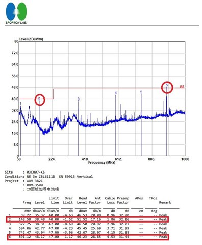
There is a project using TMDS181 in customer board. The HDMI points fail to meet the requirement of Class-B:

891MHz: over spec of 1.17dB

148MHz: the margin is only 1.52dB, which has risk.

Test results:

schematic:TMDS181 -AOM-3500_DCC SNOOP.pdf

layout: HDMI Re-timer-JOB.brd

Support need:

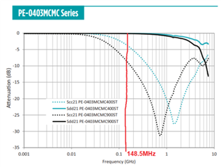
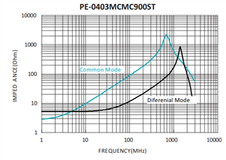
Help to suggest on how to improve the EMC performance. Whether it's related to the CMC choke selection?

BRs,

Rannie

  • Hi Rannie,

    148MHz would be the speed of the HDMI CLK signal and 891MHz would be the 5th harmonic. Its possible this is a CMC issue however I have a few questions to be sure:

    1. What CMC are you using on the HDMI_CLK lane? Ideally this CMC should be optimized for 148MHz attenuation. If you're using the same CMC on CLK as on the 6Gbps data lanes then you may need to change the CMC on the CLK lane.

    2. Can you replace the CMC on the CLK with resistors and run the EMC test again? This will give us a baseline to reference for future EMC tests.

    3. Can you show a block diagram of the test setup used for this EMC test? If the HDMI cable used is not shielded it can be a source of emissions.

    One way to improve EMC performance is to add copper shielding around parts that are prone to emissions. For example, placing copper foil around the CLK lane CMC to check whether this improves your test result. If it does, then the CMC is likely emitting the frequencies you see in your test.

    Best,

    Shane

  • Hi Shane,

    Thanks for your reply.

    1. What CMC are you using on the HDMI_CLK lane? Ideally this CMC should be optimized for 148MHz attenuation. If you're using the same CMC on CLK as on the 6Gbps data lanes then you may need to change the CMC on the CLK lane.

    Could you please help to guide how to select a suitable choke on CLK lane/DATA lane? As you known, customer's SI test is also failed due to selecting a wrong choke on DATA lane (see our discussion through email about the Adv board)  Do we have an application guide for the common choke selection in HDMI application?

    The datasheet of the choke that customer used: 1212003855-01.pdf

    148MHz would be the speed of the HDMI CLK signal and 891MHz would be the 5th harmonic.

    148MHz*5=740MHz. I'm confused why 891MHz is the 5th harmonic?

    2. Can you replace the CMC on the CLK with resistors and run the EMC test again? This will give us a baseline to reference for future EMC tests.

    Could you please help to recommend a suitable resistor value? Customer concern is too large resistor will cause SI, too small resistor will not improve the EMC test.

    3. Can you show a block diagram of the test setup used for this EMC test? If the HDMI cable used is not shielded it can be a source of emissions.

    you can see as figure for the EMC setup, yes, the cable is shielded.

    For example, placing copper foil around the CLK lane CMC to check whether this improves your test result. If it does, then the CMC is likely emitting the frequencies you see in your test.

    No improvement after adding a copper foil.

    BRs,

    Rannie

  • Hi Rannie,

    1. What you want is a CMC that attenuates the signal at 148.5MHz. I see a CMC on Digikey with the part number PE-0403MCMC900ST. In the datasheet there is an attenuation plot:

    This device would be optimal (highest attenuation) around 700MHz - 800MHz based on these plots. If you're able to find a similar part that optimizes attenuation around 148MHz that would be ideal.

    Side note: You're right about the harmonic. 891MHz would be the 6th harmonic of 148.5MHz, which is the CLK frequency for HDMI. Apologies for the confusion here.

    2. The purpose is not to improve the EMC test. The purpose is to give us a baseline of system emissions with no CMC that we can use as a reference. To do this, you can test with 0-ohm resistors.

    3. Are you able to remove the monitors/screens/devices/etc from the chamber when running the test? These could be contributing to the noise you're seeing. Please also try using multiple different cables. I see from this previous E2E that a customer has used a cable with integrated ferrites to help reduce emissions.

    4. Additionally, have you run a noise-floor test on the setup with the TMDS181 disabled? I'd like to see what the noise floor looks like before you plug in the HDMI to enable this device.

    Best,

    Shane

  • Hi Shane,

    1. What you want is a CMC that attenuates the signal at 148.5MHz. I see a CMC on Digikey with the part number PE-0403MCMC900ST. In the datasheet there is an attenuation plot:

    Do you have any recommended part? But my understanding is that the common-mode impedance curve reflects the common-mode insertion loss curve to a certain extent. Considering the packaging, impedance, and process technology, it should be difficult for a 90ohm@100MHz common-mode inductor to form a large impedance or insertion loss at 148MHz. I also checked the common-mode inductors of Murata and Panasonic, and the common-mode insertion loss listed is within 2dB of the value shown in your figure. Unless you choose a common-mode inductor with a larger value at 100MHz, the SI should also be affected.

    3. Are you able to remove the monitors/screens/devices/etc from the chamber when running the test? These could be contributing to the noise you're seeing. Please also try using multiple different cables. I see from this previous E2E that a customer has used a cable with integrated ferrites to help reduce emissions.

    We have tried different cables and monitors in different labs, and there are differences. But now we want to see if there is room for optimization of the HDMI line when the board/design is revised. In addition, the lab that Advantech pre-tests is not the same as the lab that does the final certification. If the certification fails, the certification lab will not deny the cables and monitors that their labs have verified to be problem-free in other cases just because of this case.

    4. Additionally, have you run a noise-floor test on the setup with the TMDS181 disabled? I'd like to see what the noise floor looks like before you plug in the HDMI to enable this device.

    Without the HDMI cable plugged in, there is no HDMI output. I have not tried it with the chip disabled.

    Can you provide some suggestions on how to improve the EMC performance?

    BRs,

    Rannie

  • Hi Rannie,

    Yes you are right that the common mode impedance and insertion loss curves are correlated. I don't have a recommended part in mind, so I want to clarify that the higher common mode impedance and insertion loss the CMC has at 148.5MHz, the better it will block this frequency of noise on the CLK signal. If you can't find a better CMC for 148.5MHz, we'll need to think of other ways to reduce this emission.

    the certification lab will not deny the cables and monitors that their labs have verified to be problem-free in other cases just because of this case.

    My understanding is this test should be done with only the DUT in the chamber. If there are monitors/other devices in the test chamber then you are not only measuring the EMC emissions from the DUT, you are measuring the emissions from every device in the chamber. Does the certification lab not isolate the DUT when running this test?

    • Do you have a known-good system that has passed the Class-B requirement before? You can test this known-good system with the same setup to see whether your DUT is the issue or whether the cable/devices in the chamber are the issue.
    Can you provide some suggestions on how to improve the EMC performance?

    Other than the CMC, you can lower the output swing or increase the rise/fall time of the CLK signal to help reduce EMC.

    • Lowering the output swing can be done by adjusting the Vsadj resistor, but you still need to pass the HDMI compliance swing level. 
    • There is no setting on TMDS181 to change the rise/fall time of the output signal. If you can add a capacitor between the CLKp/CLKn lines of the TMDS181 output, this can help increase the rise/fall time.

    Best,

    Shane

  • Hi Shane,

    If you can add a capacitor between the CLKp/CLKn lines of the TMDS181 output, this can help increase the rise/fall time.
    1. Should the capacitor be placed near TMDS181 output? Could you please help to give a recommend capacitor value? 
    2. Whether adding a resistor between the CLKp/CLKn lines can help improve the EMI?
    3. Is there anything that can be improved through layout?

    BRs,

    Rannie

  • Hi Rannie,

    1. Yes you should place the capacitor near the TMDS181 output. I suggest starting with 10nF and increasing the capacitance as-needed to slow the rise/fall time further. You can also reduce the capacitance to increase the rise/fall time.

    2. Adding a resistor would likely not help the EMI and will add signal reflections. I do not recommend using a resistor here.

    3. Placing GND planes around signal traces can help absorb radiated emissions. I can't see the layout from the file you sent originally. Can you send the layout file again?

    Best,

    Shane