Part Number: TUSB4020BI
Other Parts Discussed in Thread: TPD1S514
Tool/software:
Hi all
I'm attempting to use this chip in a product where we have two separate USB devices in the enclosure but we want the customer to only have to plug in one USB cable.
We don't need downstream power management, and we don't need to white-label the hub, so we are choosing to operate the hub in pin-strap mode with no eeprom and power control disabled.
My impression from reading the datasheet was that most pins have internal pullups or pulldowns that configure that pin into a reasonable "turn it on and it Just Works" type of setting, so in our prototype I've left those pins disconnected accordingly.
Unfortunately, we have been having issues with our prototype where the thing will work for a while and then suddenly quit. Or it won't boot up at all. We noticed that chips would work after reflowing and then not work again when they got back to room temperature. Using an upside-down air duster to cool the chip down to freezing would also get it to work. I've noticed that the reference designs use external pull-ups and pull-downs even where the datasheet indicates that the pins have internal pullups and pulldowns in the same direction. It sort of feels like the strength of the internal pullups and pulldowns is temperature-dependent, and they are generally too weak to actually be relied upon to hold the pin high or low at room temperature, but moving the chip away from room temperature somehow makes them strong enough to start working correctly.
Our prototype board has TEST tied directly to ground, replacing that connection with a 1k pulldown made some non-working prototype boards come to life. Some boards worked fine with TEST tied directly to ground (but had a chance of stopping work after being powered up for a while).
Specific questions:
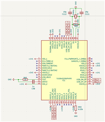
* Exactly what pins require external pullup/pulldown for basic operation with no power management or white-labeling? i.e. on the above schematic, what non-connected pins could be causing our issues.
* I already have 10k resistors in my BOM and I'd prefer to use them for pullup/pulldown if I can. The reference designs use 4.7k, is 10k too weak or will it work?
* How necessary is it to hook up USB_VBUS if we are not using power management? 90.9k is not currently in our BOM and I'd really like to avoid adding it when we don't actually need any sort of OVLO or UVLO from this chip (OVLO is provided by a TPD1S514 upstream). If spurious voltages from leaving this pin floating are responsible for our woes, can I tie it to ground?
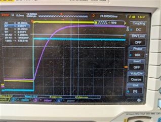
* What is the significance of the power sequencing requirements? My 1V1 and 3V3 come up simultaneously, and GRSTz hits its 2 volt threshold about 15ms later. Forcing a reset by shorting the GRSTz capacitor then releasing it doesn't make the chip come to life. Do I need to re-do my power supplies to make 3V3 come up with a deliberate delay, or does this look okay?