This thread has been locked.

If you have a related question, please click the "Ask a related question" button in the top right corner. The newly created question will be automatically linked to this question.

DP83867E: PHY Reset Requirements with AGX Orin

Part Number: DP83867E

Tool/software:

Hello, we are using the DP83867E as a RGMII PHY connected to a Jetson AGX Orin and struggle to get a stable connection.

We have RX_CTRL strapped to Mode 3 and the remaining strap pins set to Mode 1.

During testing we have been able to get a network link by leaving the RESET_N pin disconnected from the Jetson PHY_Reset, and connecting the RESET_N pin to VDDIO through a RC circuit so that after a small delay the pin gets pulled up and stays high. With this setup we have verified that our hardware setup is correct, and we are able to have successful MDIO communication and internet connection.

When having the Jetson PHY_Reset connected we observe an issue where exchanging MDIO messages fails and the reset line gets pulled low by the Jetson.

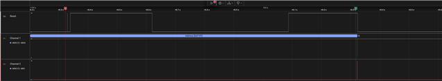
After connecting a logic analyzer, we are able to see the Jetson PHY_Reset behavior and MDIO packages. Marker 0 is where the reset sequence starts. Marker 1 is when MDIO communication is attempted.

jetson_reset_and_mdio

Zoomed in section of the attempted MDIO communication:

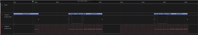
The Jetson attempts to read the registers 0x02 and 0x03, but the operation fails. The PHY does not pull down the MDIO line during turnaround and a value of 0xFFFFF is read, even though at that time the reset is high.

What could be causing this failure to read the MDIO data ?

Is it a viable approach to just have the RESET_N pulled up through a RC circuit and not connected to the Jetson ?

  • Hello,

    When the Jetson connection on reset is present, the SMI functionality fails, while when this connection is absent, the SMI functionality is all good? This may lead to initialization concerns if the reset may be affecting the SMI functionality. It is viable to have RESET pulled up; in fact there is internal PU resistor on the pin if the external pin is left not connected. Having external connection is warranted when customers want to externally pull down the pin for intentional HW reset.

    Sincerely,

    Gerome

  • Hello Gerome,

    Correct, when the Jetson reset connection is present the SMI functionality fails, and when it's not connected but pulled up through an RC the PHY works but also not always, around 70% of the time.

    So is it ok to not have the reset line connected ? If we can confirm that the PHY can be fully functional without it then we could remove it from our design.

    Are you able to give any insight based on the images from the logic analyzer? The attached section shows a case where the PHY went through a reset sequence but still fail to respond on MDIO. Could it be related to timing of the pulses?

  • Hello,

    It appears that the issue lies on the SoC controlling the reset line then. It could be issues with initialization, or resetting during a transaction which confuses the state machine.

    If you are okay with not having the line connected to SoC, PHY can still function with this pin PU.

    Sincerely,

    Gerome

  • Hello,
    I'm Patryks colleague working on the same problem currently.
    We have already had a long thread with NVIDIA on possible errors on that side.
    Neither we nor NVIDIA could find a misconfiguration on that end.
    We set CONFIG_DP83867_PHY=y before building the kernel and confirmed it is present on the running system.

    Would you be able to confirm that the following device-tree looks to be correct?

    // SPDX-License-Identifier: GPL-2.0-only
    /*
     * Device Tree Overlay for RGMII Gigabit Ethernet PHY
     * This overlay configures the EQOS Ethernet controller to use an external PHY
     * connected via RGMII interface.
     * Based on https://docs.nvidia.com/jetson/archives/r36.4/DeveloperGuide/HR/JetsonModuleAdaptationAndBringUp/JetsonAgxOrinSeries.html#for-rgmii
     */
    
    /dts-v1/;
    /plugin/;
    
    #include <dt-bindings/gpio/tegra234-gpio.h>
    #include <dt-bindings/interrupt-controller/irq.h>
    #include <dt-bindings/net/ti-dp83867.h>
    
    / {
    	overlay-name = "RGMII Gigabit Ethernet PHY";
    
    	compatible = "nvidia,tegra234";
    
    	fragment@0 {
    		target-path = "/bus@0/ethernet@2310000";
    		__overlay__ {
    			status = "okay";
    			nvidia,mac-addr-idx = <0>;
    			nvidia,max-platform-mtu = <8000>;
    			nvidia,pause_frames = <0>;
    			local-mac-adress = [1a 2b 3c 4d 5e 6f];
    			phy-mode = "rgmii-id";
    			phy-handle = <&phy>;
    			nvidia,phy-reset-gpio = <&gpio TEGRA234_MAIN_GPIO(G, 5) 0>;
    
    			mdio {
    				compatible = "nvidia,eqos-mdio";
    				#address-cells = <1>;
    				#size-cells = <0>;
    
    				phy: phy@0 {
    					reg = <0>;
    					nvidia,phy-rst-pdelay-msec = <224>; /* msec */
    					nvidia,phy-rst-duration-usec = <10000>; /* usec */
    					interrupt-parent = <&gpio>;
    					interrupts = <TEGRA234_MAIN_GPIO(G, 4) IRQ_TYPE_LEVEL_LOW>;
    					// Extra settings based on https://e2e.ti.com/support/processors-group/processors/f/processors-forum/563409/linux-66ak2l06-how-to-configure-dp83867-ethernet-phy-in-the-device-tree/2073476#2073476
    					compatible = "ethernet-phy-ieee802.3-c22";
    					tx-fifo-depth = <DP83867_PHYCR_FIFO_DEPTH_4_B_NIB>;
    					rx-fifo-depth = <DP83867_PHYCR_FIFO_DEPTH_4_B_NIB>;
    					ti,max-output-impedance;
    					// ti,clk-output-sel = <DP83867_CLK_O_SEL_CHN_A_RCLK>;
    					ti,rx-internal-delay = <DP83867_RGMIIDCTL_2_25_NS>;
    					ti,tx-internal-delay = <DP83867_RGMIIDCTL_2_75_NS>;
    				};
    			};
    		};
    	};
    
    	fragment@1 {
    		target-path = "/bus@0/ethernet@6800000";
    		__overlay__ {
    			status = "disabled";
    		};
    	};
    };


  • Hi Alexander,

    I had a colleague take a look at the device tree. One concern is the PHY-RST- lines. It is unclear what exactly these lines are doing and why there are two if the granularity could theoretically be taken care of in the usec. However, since RESET is the topic of concern here, it may be helpful to electrically scope out the RESET line to understand what is going on here compared to when the SoC is not controlling the DUT's reset.

    Sincerely,

    Gerome

  • We also asked about these settings with NVIDIA.
    The first one is the delay between the reset and the SoC trying to communicate with the PHY via MDIO.
    The second one is the duration for which the reset line is pulled low.

    reset-delay:
        description:
          RESET pulse width in microseconds. It applies to all MDIO devices
          and must therefore be appropriately determined based on all devices
          requirements (maximum value of all per-device RESET pulse widths).
    
    reset-post-delay:
        description:
          Delay after reset deassert in microseconds. It applies to all MDIO
          devices and it's determined by how fast all devices are ready for
          communication. This delay happens just before e.g. Ethernet PHY
          type ID auto detection.


    About scoping out the reset line, I'm not sure what exactly you mean.
    We have done that at least with the logic analyzer and the reset signals the SoC sends are the same, no matter if the PHY is connected to it or not. (Except that the reset line is not being pulled low if the SoC successfully establishes communication via MDIO in the disconnected case)
    Measuring the PHY-side of the reset line, when it is disconnected just keeps the signal out of reset for the whole time.

  • Hello,

    A logic analyzer would digitize the result to be pure high/low, while a scope would provide better insight on whether or not there is signal integrity issue (rise/fall issues, reflection, setup/hold, weird glitch, etc). I wanted to see this information as it could provide better insight on the electrical characteristics of the timing.

    Sincerely,

    Gerome

  • # Oscilloscope
    We have checked the analog signal with the Logic Analyzer. The signal is not as precise as with an oscilloscope, but it looked pretty much how we expect, with good step function behavior.

    # Strap Resistors
    We have also looked into the configuration of the PHY via strap resistors. Except for the required one on RX_CTRL, we left everything as is.
    First we had LED_0, LED_1 and LED_2 connected to ground over some LED + a 51Ohm resistor (instead of the 470 Ohm one that was recommended). Removing the LEDs completely (leaving the connection open) did not change the behavior.

    Does leaving all strap resistors (except the required one) in Mode 1 (open/open) seem correct?

    # Device Tree
    Where do we check which of the options that `dt-bindings/net/ti-dp83867.h` provides need to be set? Are the ones we use correct?

  • Hello,

    The provided strapping should be okay. It would be best to confirm that your settings are intact via Reg 0x6E and Reg 0x6F. The behavior you are reporting initially indicates that misstrapping could be occuring, where the DC bias presented by the internal resistor on the strap pin is disrupted by external factors outside the PHY. In the case where SMI is unresponsive, if the device was discovered on a different PHY address, this would further solidify this hypothesis.

    Sincerely,
    Gerome