This thread has been locked.

If you have a related question, please click the "Ask a related question" button in the top right corner. The newly created question will be automatically linked to this question.

SN65HVD234: CAN EMC Consideration

Part Number: SN65HVD234

Tool/software:

Hi,

I am reading application report "SLLA337", which is related to 3.3V CAN.

Several questions:

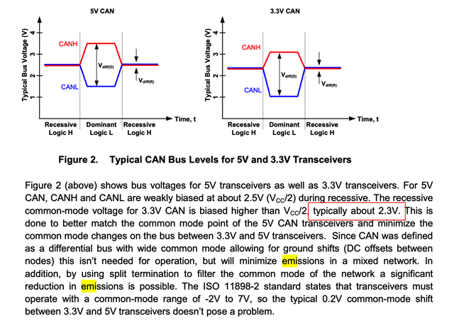
1. To minimize EMC, I need to keep the common mode voltage of CAN bus recessive state same as dominant state, so there is no emission. And it does not matter that this common mode voltage is VDD/2 or VDD/3, as long as it is same for recessive and dominant. Am I correct? 

2. For this reason, TI sets 3.3V CAN common mode voltage as 2.3V not 1.65V, in order to match 5V CAN common mode voltage of 2.5V. But why not directly set 2.5V, is because CANH-CANL voltage range?

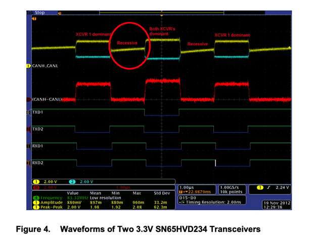
3. For two 3,3V CAN communication, they recessive voltage goes up slowly? Doesn't it cause EMC issue?

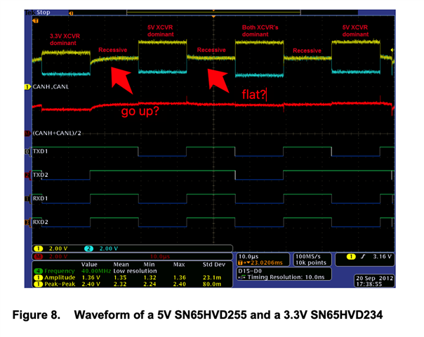
4. When 3.3V CAN talks to 5V CAN, why recessive voltage sometimes goes up, sometimes is flat?

When 3.3V CAN talks to 5V CAN, bus recessive common mode voltage is 2.5V or 2.3V? Or some voltage between 2.5V and 2.3V?

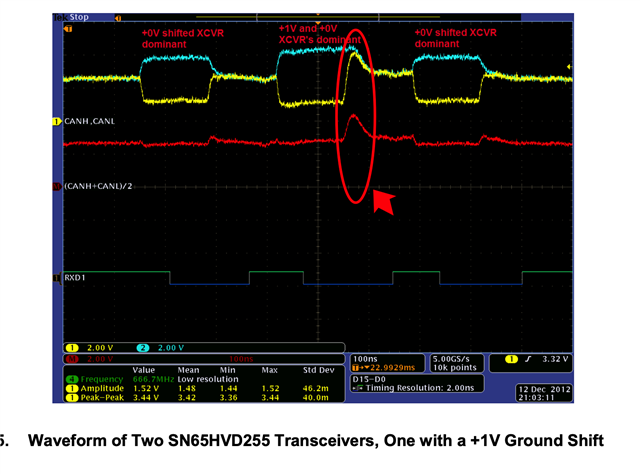
5. Why ground shit causes common mode voltage difference at dominant to recessive? Not during dominant state?

Regards

Nic

  • Hi Nic,

    1. Yes

    2.  This is because 3.3 V do not provide as much headroom as 5 V I.e., pushing for 2.5 V will reduce the available swing and further push the device's output into non-linear regions or close to the supply limits and 2.3 V is a compromise to ensure reliable differential signal still matching the 2.5 V standard.

    3. A slower edge within the spec required for reliable CAN communication typically produces fewer high frequency emissions. Hence, lowers radiated emissions.

    4. If the 3.3 V CAN is not actively driving, the 5 V CAN will dominate to the 2.5 V for the "going up". For flat, both devices contribute to the bus bias and settles the voltage at an intermediate level.

    The exact value is between 2.3 V and 2.5 V depending on the bus conditions for which device is actively driving or releasing the line. This is normal and expected when interfacing devices with different supplies.

    5. The device actively drives the bus with a strong differential signal during the dominant state. Hence, this is why the device masks minor ground potential differences when the driver's output impedance is low and forces the bus to the desired voltage levels.

    The bus is not actively driven in the recessive state and biased by the termination instead. Such ground shifts will be more apparent as the bus voltage is defined relative to GND while causing common mode voltages to shift when in high impedance compared to when actively driven, thanks.

    Best Regards,

    Michael.

  • For 3, do you mean the slowly going-up recessive voltage is on purpose? Then why it only exist  in 3.3V CAN, not in 5V CAN?

  • Hi Zhihong,

    5 V CAN with a higher supply voltage implies more headroom for driving the bus. The bias network and termination are designed to achieve faster transitions that follows CAN standard timing without needing to stretch the recessive transition unlike the 3.3 V CAN, thanks.

    Best Regards,

    Michael.