Part Number: TMUXHS4612
Tool/software:
Hi
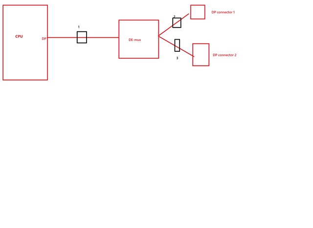
The schematics are all SMA connectors. Is there a DP connector? Also, are the MUX output signals, data, clk, and aux all directly connected to the DP connector with 0 ohm?

Part Number: TMUXHS4612
Tool/software:
Hi
The schematics are all SMA connectors. Is there a DP connector? Also, are the MUX output signals, data, clk, and aux all directly connected to the DP connector with 0 ohm?