


Other Parts Discussed in Thread: LMH1297
Tool/software:
Hello SDI engineers and LMH enthusiasts,
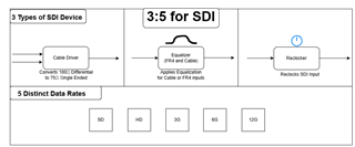
Figure 1 - 3:5 for SDI
In this E2E FAQ, I will be discussing GND plane layout best practices for SDI designs. In cable driver designs, see figure 1, SDI data transitions between 50 ohms differential and 75 ohm single ended characteristic impedances as the means of transport.
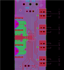
Figure 2 - LMH1297 layout
Figure 2 illustrates the way TI adjusts the PCB layout to content with this change in characteristic impedance change. The green section shows the GND reference at Layer 3 of the board for the 75 ohm single ended signals. The increase in distance between the traces and the reference plane increases the characteristic impedance on the trace.
All current must flow in a closed loop and return to its source. The goal of using a reference plane is to reduce emissions like crosstalk. The current will return to its source somehow, and it is in the designers best interest to ensure that the flow is predictable.
Best regards,
Nick