Part Number: THVD2410
Other Parts Discussed in Thread: THVD1400,
Tool/software:
Hi Team:
i know to config out why the 485 device have different Vth setting, so i compare THVD2410 VS THVD1400 here.
THVD1400:
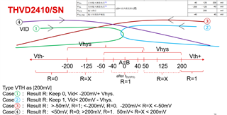
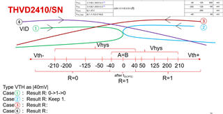
THVD2410:
First, for THVD1400, i summary like below VID w/ Vth±:
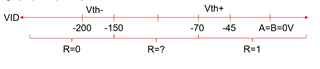
base on it ,we can know when the A=B=0V, The Vid=0V>-45mV, and make the R output 1, and the -45mV maximum value ensures that even under the worst process, VID=0V still has at least 45mV noise margin (0V-(-45mV)=45mV).
so what about the VID range of -150~-70mV? what s the R output behavior?
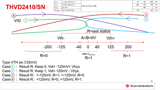
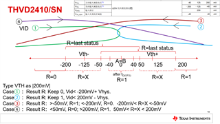
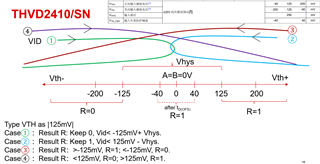
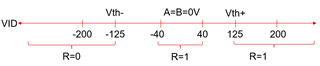
For THVD2410, it will have fail-safe mode to make sure the Vid range (-40~40 ) will make R output 1.
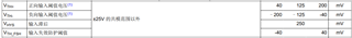
and for the Vth+ and Vth-, does it also get the R=0 when Vid<-40mV? and R=1 when Vid >40mV? or we should follow below ±125 threshold? but what about the Vid drop into the range of (-125~-40) and (40~125)?
tks for the comments here.