Other Parts Discussed in Thread: DP83869, , USB-2-MDIO, SK-AM62B-P1
Tool/software:
Hi,
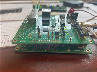
I have two DP83869EVMs, and I have connected them together like this:
RX_CTRL -> TX_CTRL
TX_CTRL -> RX_CTRL
RX_D3 -> TX_D3
TX_D3 -> RX_D3
RX_D2 -> TX_D2
TX_D2 -> RX_D2
RX_D1 -> TX_D1
TX_D1 -> RX_D1
RX_D0 -> TX_D0
TX_D0 -> RX_D0
RX_CLK -> GTX_CLK
GTX_CLK-> RX_CLK
GND -> GND
So, EVM1 of DP83869 will be configured as Fiber-RGMII, and EVM2 will be configured as Copper-RGMII. I will connect both boards RGMII back-to-back. The following is how the setup looks:
PC<---> UMC-GA1F1T(Electrical to Fiber) <---> EVM1(Fiber-RGMII) <---> EVM2(RGMII-Copper) <---> Host(can be ping - 192.168.137.2)
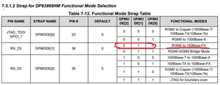
Straps settings:
OP_Mode[2:0] = 000 - for RGMII-Copper operation
OP_Mode[2:0] = 001 - for RGMII-Fiber operation
Result:
Pinging 192.168.137.2 with 32 bytes of data:
Reply from 192.168.137.110: Destination host unreachable.
Reply from 192.168.137.110: Destination host unreachable.
Reply from 192.168.137.110: Destination host unreachable.
Reply from 192.168.137.110: Destination host unreachable.
Ping statistics for 192.168.137.2:
Packets: Sent = 4, Received = 4, Lost = 0 (0% loss)