This thread has been locked.

If you have a related question, please click the "Ask a related question" button in the top right corner. The newly created question will be automatically linked to this question.

DP83822I: DP83822

Part Number: DP83822I

Tool/software:

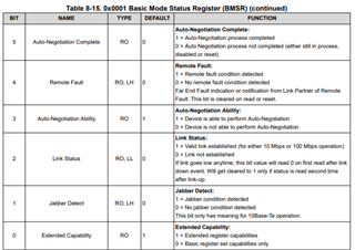
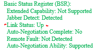
I integrated dp83822 PHY in a unit. The configuration is as follows: Duplex mode Full Duplex, Speed 100 Mbps, Auto-Negotiation Disabled, Loopback Disabled, Reset Inactive, Collision test Disabled. I also have the SD pin enabled. This unit directly interfaces with a fiber module. The fiber module interfaces with 10 other units. When I power up the system from cold and dark, I get a communication link error message from my system. The link error only happens to this units that has the DP83822 PHY. I power cycle the unit and the fault goes away (clears). The issue happens after about 4 and half minutes of the initial power up (it is consistently happening). The receive error counter and the false carrier error counters show higher count values right before the issue happens. The process I have during power up is: custom config gets loaded to the config register then I do a soft reset of the PHY and a reset of the clock. I would like to understand the root cause and address it accordingly. It would be really awesome if you can shed some light on this.

  • Hi Ed,

    When the link communication error happens, do you notice the link drop on the MDI side of the PHY? This would be indicated by LED_0 going low, or reading bit 2 of register 0x0001:

    If the link does not drop on the MDI side, it suggests an issue with the MAC (MII) interface. Can you show a block diagram of the system with the MAC/MII interface included?

    Best,

    Shane

  • Link sows UP through out.

  • Hi Shane,

    Thank you for your response. I appreciate it. Link Status shows UP through out the event. Below is a decoded version of the register data: 

  • Thanks Ed,

    I'd like to check the signal path between the PHY and the fiber module to rule out any implementation issues on this end. 

    1. Can you probe the signal from the fiber module and show the eye diagram near the receiver of the PHY? These would be the RD_P/M pins

    2. Which fiber module/connector part(s) are you using in this design? It would be good to see these for more context on your system. If you can share the schematic that would be ideal.

    3. If you cannot provide the schematic, can you verify that your implementation follows the example in section 9.2.2 of the DP83822 datasheet? Here is that example for reference:

    Best,

    Shane

  • Also for item 1, it would be good to see the signal eye diagram near the PHY receiver in both the working and failing conditions. This should tell whether the signal itself is degrading after 4 and 1/2 minutes.

  • Hi Shane,

    This is the high level of the schematic that shows the PHY and the End System connection.

  • Hi Ed,

    Were you able to get an eye diagram from the PHY MDI receivers? 

    The block diagram is helpful to see, however it doesn't show details on the MDI connection between the PHY and the fiber module. Can you verify this connection follows the datasheet example?

    For my own understanding, how do you split the MII signal from each PHY to two MACs? Is there an MII MUX in this signal path?

    Best,

    Shane

  • Hi Shane,

    The connection does follow the datasheet example you provided above. 

    Yea, I have a MUX stage between the PHY and the MAC.

    Best,

    ED.

  • Just FYI: My colleagues said they did the eye diagram on both cases (faulted and working conditions) and they didn't see a difference. 

  • Receive error and false error counters are based on the MDI side of the PHY. I suspect this is an issue with the MDI Fiber interface or with the power up timings on the DP83822. If the datasheet timings are not met, it can put the PHY into a bad state.

    The process I have during power up is: custom config gets loaded to the config register then I do a soft reset of the PHY and a reset of the clock.

    When you do the clock reset, is the clock signal disrupted to the PHY? The clock signal should be stable before the PHY power up sequence and stay stable throughout the PHY operation:

    Can you check that your system meets the timing requirements in the DP83822 datasheet for power up?

    Best,

    Shane

  • Hi Ed,

    Were you able to make progress on this issue?

    I'll mark this as resolved due to inactivity. You can follow up here with future updates and I will continue to reply.

    Best,

    Shane