This thread has been locked.

If you have a related question, please click the "Ask a related question" button in the top right corner. The newly created question will be automatically linked to this question.

TDP0604: TDP0604 Implementation Support

Part Number: TDP0604

Tool/software:

Good Morning!

I've recently been trying to convert a DDI output from an Intel based COM module to a compatible HDMI signal for connection to an external monitor.

The DDI port is configured as a DVI output, and works correctly with an evaluation board using the circuit attached titled "Evaluation Board DVI Output".

Evaluation Board DVI Output.pdf

I have used a slightly different level shifter to that shown in the evaluation board schematic. I have opted to use the TDP0604, but have unfortunately had no luck in getting it to work. I found an approved design on this TI forum for DVI to HDMI using the TDP0604, but again am struggling to get anything to display on the external monitor I have connected. The design I mention can be found here:

https://e2e.ti.com/support/interface-group/interface/f/interface-forum/1207095/tdp0604-tdp0604

Between the evaluation board design and the approved schematic I mention, there is a difference in the input coupling. The approved design uses 0ohm resistors (DC coupled) and the evaluation board uses 100nF caps (AC coupled). I've tried both methods but neither seem to be the cause of my issue. Are you able to clarify if I should be using AC or DC coupled for a DVI configured DDI port?

I have also found a similar design in use here:

https://e2e.ti.com/support/interface-group/interface/f/interface-forum/1461534/tdp0604-sch-review?tisearch=e2e-sitesearch&keymatch=tdp0604#

This approved schematic uses a DDI port level shifted to a HDMI connector. I'm not certain how the DDI port is configured in this design, so it may be that the AC coupling is appropriate here.

The document below, HDMI Level Shifter Design, is the board I have designed and been trying to get to work. This is used is strap mode.

HDMI Level Shifter Design.pdf

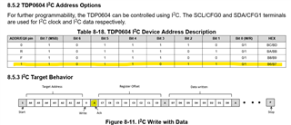
The configuration using the straps is as follows:

  • Mode, 17, 1k pulldown
  • Addr/Eq0, 35, float
  • EQ1, 8, float
  • CFG0, 21, 10k pulldown
  • CFG1, 22, 10k pulldown
  • LIN_EN, 5, 1k pulldown
  • AC_EN, 23, 1k pulldown
  • HPDOUT_SEL, 2, float
  • CTLEMAP_SEL, 4, 20k pulldown
  • TXPRE, 29, float
  • TXSWG, 38, float

I have also tried the following:

  • ADDR/EQ0, 35, 1k pulldown.
  • AC_EN, 23, 1k pullup
  • 100nF cap added to EN, 7.
  • Changed R1109 and R1110 to 1k8.
  • Removed L1100 to L1103 and shorted pads using wire.
  • Double checked the pinouts and net connections multiple times and can't say any incorrect connections.
  • Verified HPD_OUT changes to 5V when external monitor is connected. This drops back to 0V on disconnection.
  • Reading through the datasheet for each strap pin and ensuring correct configuration.
  • Verified all power pins are at 3V3.
  • The differential pair outputs of the TDP0604 jump to 3V3 when a cable is connected, but drop to about 2V with nothing connected.

I'm at a bit of a loss as to what could be causing my issue. I was hoping you would be able to have a look at my design and see if you can spot any problems, and maybe suggested some possible things to try?

I look forward to your response!

Tom

  • Further to the above testing, I've just compared the voltages at the input AC coupling capacitors on both the working evaluation board and my design. Both boards show approx. 0.5V at the DDI side of the caps, however where the (working) carrier board has approx. 0V on the other side of the caps, my (not working) design has 3V3. 

    It seems to me that the TDP0604 is not configuring properly.

    I have modified the design slightly to ensure the EN pin comes up after all other power and strap pins, so I don't believe the straps are being sampled incorrectly.

  • Hi Tom, 

    Are you able to clarify if I should be using AC or DC coupled for a DVI configured DDI port?


    AC Coupled is used when the incoming signal is DP++, and DC coupled is used when the incoming signal is DVI/HDMI. 
    Since your port is DVI, please treat it as DC coupled. Therefore, please use 0 ohm resistors on the path.

    Removed L1100 to L1103 and shorted pads using wire.

    Please use 0 ohm resistor rather than wires for signal integrity. 

    Looking at the schematic, I am not sure if your common mode choke is for HDMI signals. Please use common mode choke with cut off frequency of twice the HDMI data rate you are working on. We recommend Murata NFG0QHB372HS2D. 

    For your schematic, you are missing a few of our recommendation:
    1. HPD_OUT is recommended to be pulled down to GND with 220k resistor. 
    2. Please pull down CFG0 and CFG1 to GND with 1k ohm resistor. 
    3. Please disable AC_EN for your use. 1k pulldown to GND. 

    Verified HPD_OUT changes to 5V when external monitor is connected.


    In addition, HPD_OUT signal needs to be 3.3V, not 5V. Please verify this since you are using the 0604 level shifter. 

    But, it seems like your HPD signal is working. 
    Can you verify that the source uses open-drain, not push-pull? Our DDC buffer level shifter will not work if the source uses push-pull. 

    If you can verify that DDC buffer is working and the source is getting EDID information, I suggest to try all the EQ settings on the pin-strap mode with CTLE MAP C (that is 20k pulldown to GND). 

    Please let me know. 

    Best, 
    J

  • Good Morning J,

    Thanks for your response.

    I have now made the following changes:

    1. 220kohm pulldown resistor to HPD_OUT.
    2. Replaced CFG0 and CFG1 pulldowns with 1kohm.
    3. Pulled AC_EN low through a 1kohm pulldown.
    4. Pulled CTLEMAP_SEL low through a 20kohm pulldown.

    Regarding the HPD_OUT voltage level; this is actually at 3V3 when a sink is connected (just a typo in the previous posts), and the HPD_IN pin is at 5V. 

    I've asked for clarification about the output type of the I2C/DDC pins of the COM module, and will let you know when I have more info.

    Kind regards,

    Tom

  • Hi Tom, 

    While you wait, if you have an i2c controller, you can try to directly try to read EDID information of the monitor from the DDC buffer. You can directly connect to the sda and scl of the DDC buffer from the low voltage side of TDP0604 and send read 128 bytes of register 0x50.

    Please let me know if you have any questions about this. 


    Best, 
    J

  • Thanks for the idea J, I'll give it a go.

    Tom

  • Hi Tom,

    Please let me how it goes.

    Best,

    J

  • Morning J,

    I don't seem to be having much luck talking to the device unfortunately. Despite trying a few different things, I can't seem to get an ACK from the device to confirm I've addressed to it correctly.

    I have the ADDR/EQ0 pin pulled up, which I believe means the device address should be B6/B7, but all I seem to get in return when I address it is a 0 for the first ACK. I have also tried presenting the address in different ways using bitshifting (hence '5B' as the address in the code below) for example but gotten nowhere.

    This is the code I'm using, along with an Arduino Nano. I've double checked the hardware connections and everything seems to be correct, so I'm falling down at the software level. 

    Could it be the device isn't configuring correctly from power on? Is there any way for me to check through hardware if it is? Do you have any example code that you're certain talks to the device correctly?

    I'm still waiting on the outstanding info from the supplier.

    Kind regards,

    Tom

  • Hi Tom,

    I apologize for the confusion. If you want to read the EDID information of the monitor, you would have to directly connect to the DDC buffer of 0604. This would mean the slave address mentioned in the datasheet doesnt work. If you directly connect to the DDC buffer ( i mean connect to LV_DDC_SCL and LV_DDC_SDA pins), reading bytes from devicd address 0x50 should return you information if DDC buffer works.

    For I2C of the device itself to work, you would have to put the mode pin into float. Could you please check if that modification was done? 

    If the mode pin is set to float and you connected to SDA and SCL pins of 0604, you should be able to get i2c response from the device address you mentioned (B6/B7), for any acknowledgement to see if the device is even on for i2c mode.

    Best,
    J