This thread has been locked.

If you have a related question, please click the "Ask a related question" button in the top right corner. The newly created question will be automatically linked to this question.

DP83825I: Output waveform is not generated

Part Number: DP83825I

Tool/software:

Hi team,

Customer can't see waveform for compliance test by below procedure and setting.

Compliance Target: 10BASE-T
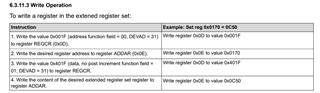
Procedure

1. Disable auto-negotiation: BMCR_Register bit12 0x0

2. select 10Mbps: BMCR_Register bit13 0x0

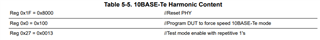
3. Mode is selected by COMPT_Register: 1001 or 0100 or 0011

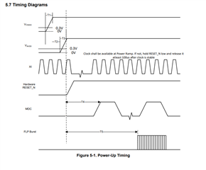
BTW, customer noticed voltage ramp might be a problem. If T1 or T3 ramp up before 0.5ms passed, what will be happen?

Best regards,

Hayashi

  • Hayashi-san

    For compliance testing, please see this app note, https://www.ti.com/lit/an/snla266b/snla266b.pdf

    Since COMPT_Register is an extended register, are they following the extended register read and write procedure? 

    Can you please share a diagram of their power up sequence? They must meet the DP83825 power-up timing requirement, otherwise the device operation is not guaranteed.

    Thanks

    David

  • Hi David,

    I’m Kurumi, AFAE in Japan and I’m taking over this account from Hayashi-san.


    For the extended register read and write procedure, does it mean we need to follow those 4steps before “Disable auto-negotiation : BMCR_Register bit12 0x0”?


    For the power up sequence, they use same 3.3V for AVDD and VDDIO. Would it be a problem?

    Also, there is a possibility that the 3.3V line being too fast, 0.27ms voltage ramp duration. The 3.3V is from PMIC, which the customer cannot change the setting. So I believe we need external circuit to make it slow. What would be the possible option? Using RC filter? Do you happened to know other method?


    Best regards,

    Kurumi

  • Kurumi-san

    Please see my response below

    For the extended register read and write procedure, does it mean we need to follow those 4steps before “Disable auto-negotiation : BMCR_Register bit12 0x0”?

    Please see the script below. The 4 steps are to write to register 0x27, so you want to do it after the write to register 0x1F and 0x0.

    For the power up sequence, they use same 3.3V for AVDD and VDDIO. Would it be a problem?

    No, but I want to make sure they are meeting the DP83825 power up sequence as shown below.

    Thanks

    David 

  • Hi David,

    Thank you so much for your additional explanation on extended register. The customer confirmed the signal communication working correctly.

    For supply sequence, I believe that using same 3.3V for AVDD and VDDIO is fine. But the voltage ramp duration should be within the datasheet spec which is 0.5ms. It seems the 3.3V line is now have ramp duration of 0.27ms. As mentioned, the duration is from PMIC setting which the customer cannot change. I asked them to add RC filter, but that is not acceptable, either. Do you know any other possible way to achieve 0.5ms duration?

    Best regards,

    Kurumi

  • Hi Kurumi,

    David is on travel so I'll help to support this thread. Can you check that the customer is following the power supply decoupling recommendations for DP83825 in their design?

    Adding capacitance to the power line can help to increase the ramp duration.

    Best,

    Shane

  • Hi Shane,

    Thank you for your reply.

    Yes they are using decoupling cap already, and it is still 0.27ms.

    Best regards,

    Kurumi

  • Hi Kurumi,

    From my understanding:

    • Customer is using a PMIC setting to control the rise time. This cannot be changed
    • Customer doesn't want to add an RC circuit

    Unfortunately there isn't much we can do from a PHY perspective. It falls on the customer to operate the DP83825 within the datasheet specs. While the device may work outside of the spec, we cannot guarantee its performance.

    I recommend adding a RC delay circuit or using a PMIC with a slower ramp time. 

    Best,

    Shane

  • Hi Shane,

    Understood, thank you for your comments.

    Best regards,

    Kurumi