Other Parts Discussed in Thread: SN65DSI83
Tool/software:
hello,
we are now develop one product with raspberry pi cm4,
and it has a 1920x1080 dual-link LVDS screen.
we use ti-sn65dsi84 to convert cm4 mipi dsi video output to duall-ink lvds screen
and now meet some problems.
(1) screen flicker after some time
when use dsi 3-lane or 2-lane, even 1-lane, the screen can work correctly. but it's not stable.
after working a long time, sometimes 2-3 days .or sometimes 2-3 weeks, the screen will flicker with multi-color. just as the video I uploaded.
it's not the screen 's business. we tried to disconnect the screen LVDS interface and replace with another same kind screen, it flicker too.
and if we touch the screen to change the page, it will turn to normal, but can only keep normal for 3-5 seconds, then it flicker again.
why is it happening? and how to solve it?
(2) when use dsi 4-lane, screen shows nothing
we try to use dsi 4-lane, we edit the devicetree data-lanes = <1 2 3 4>; but the screen shows nothing.
I can see the screen correctly with VNC tool, so there must be something wrong in the raspberry dsi signal, or in the sn65dsi84 bridge.
I read the registers value, and seems OK.
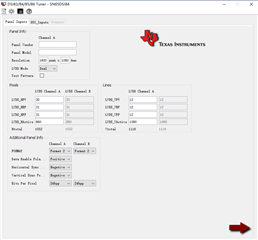
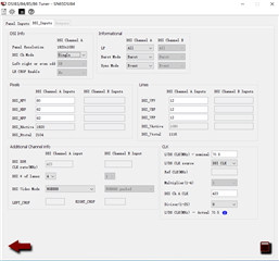
and I have read the ti document, use the dsi tunner v2.1 tool to generate CSR value. but still no use.
(3) kernel driver sn65dsi83.c bug?
when compare the dsi tunner CSR value with the ti-sn65dsi84 kernel offical driver value (kernel / driver / gpu / drm / bridge / ti-sn65dsi83.c)
I find that the horizontal porch registers (0x2c 0x34 0x38) are not the same. values in kernel driver are 2-times than the values generated by dsi tunner tool.
REG_VID_CHA_SYNC_DELAY_LOW 0x28
REG_VID_CHA_HORIZONTAL_BACK_PORCH 0x34
REG_VID_CHA_HORIZONTAL_FRONT_PORCH 0x38
and after test, I think the values in dsi tunner tool is correctly, the value generated in ti-sn65dsi83.c is correct for sn65dsi83 single-link lvds , but should be half for sn65dsi84 dual-link lvds.
am I right?
should the kernel driver ti-sn65dsi83.c adjust to be compatible for sn65dsi84?
thanks.
attachments:
(1) video of screen flicker
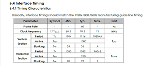
(2)screen timing
(3) my linux device tree overlay.dts
/dts-v1/;
/plugin/;
#include <dt-bindings/gpio/gpio.h>
#include <dt-bindings/pinctrl/bcm2835.h>

/ {
        compatible = "brcm,bcm2835";

        /* PWM0 function */
        fragment@0 {
                target = <&gpio>;
                __overlay__ {
                        pwm_pins: pwm_pins {
                                brcm,pins = <19>;
                                brcm,function = <BCM2835_FSEL_ALT5>; //PWM0_1
                                brcm,pull = <0>;
                        };
                };
        };

        fragment@1 {
                target = <&pwm>;
                frag1: __overlay__ {
                        pinctrl-names = "default";
                        pinctrl-0 = <&pwm_pins>;
                        assigned-clock-rates = <50000000>;
                        status = "okay";
                };
        };

        fragment@2 {
                target-path = "/";
                __overlay__ {
                        //#gpio-cells = <2>;
                        /* Panel backlight through PWM0-1 on GPIO 19 */
                        backlight_lvds: backlight {
                                compatible = "pwm-backlight";
                                pwms = <&pwm 1 1000000 0>; /* Period of 1000000ns means 1KHz */
                                brightness-levels = <0 1000>;
                                num-interpolated-steps = <100>;
                                default-brightness-level = <1>;
                                //enable-gpios = <&gpio 21 GPIO_ACTIVE_HIGH>;     /* Backlight enable */
                        };

                        panel: panel {
                                compatible = "panel-lvds";
                                backlight = <&backlight_lvds>;

                                label = "AUO:G156HAN";

                                /* Physical dimensions of active area */
                                width-mm = <344>;
                                height-mm = <194>;

                                data-mapping = "vesa-24";

                                panel-timing {
                                        /* IF the hactive and porches in the datasheet are used for a single LVDS channel */
                                        /* since we use dual LVDS channel, Horizontal paramter and clock must double*/
                                        //clock-frequency = <141000000>;        //140880000 对应 1920+184
                                        clock-frequency = <125000000>;
                                        hactive = <1920>;
                                        hsync-len = <60>;
                                        hfront-porch = <62>;
                                        hback-porch = <62>;

                                        vactive = <1080>;
                                        vsync-len = <12>;
                                        vfront-porch = <12>;
                                        vback-porch = <12>;
                                };

                                ports {
                                        #address-cells = <1>;
                                        #size-cells = <0>;
                                        port@0 {
                                                reg = <0>;
                                                dual-lvds-odd-pixels;
                                                panel_in_a: endpoint {
                                                        remote-endpoint = <&bridge_out_a>;
                                                };
                                        };
                                        port@1 {
                                                reg = <1>;
                                                dual-lvds-even-pixels;
                                                panel_in_b: endpoint {
                                                        remote-endpoint = <&bridge_out_b>;
                                                };
                                        };
                                };
                        };
                };
        };

        fragment@3 {
                target = <&i2c_csi_dsi>;
                __overlay__ {
                        #gpio-cells = <2>;
                        #address-cells = <1>;
                        #size-cells = <0>;
                        status = "okay";

                        bridge@2c {
                                compatible = "ti,sn65dsi84";
                                reg = <0x2c>;
                                enable-gpios = <&gpio 0 GPIO_ACTIVE_HIGH>;

                                ports {
                                        #address-cells = <1>;
                                        #size-cells = <0>;

                                        port@0 {
                                                reg = <0>;
                                                bridge_in: endpoint {
                                                        remote-endpoint = <&dsi_out>;
                                                        data-lanes = <1 2 3 4>;
                                                        //data-lanes = <1 2 3>;
                                                };
                                        };

                                        port@2 {
                                                reg = <2>;
                                                bridge_out_a: endpoint {
                                                        remote-endpoint = <&panel_in_a>;
                                                };
                                        };

                                        port@3 {
                                                reg = <3>;
                                                bridge_out_b: endpoint {
                                                        remote-endpoint = <&panel_in_b>;
                                                };
                                        };
                                };
                        };
                };
        };

        fragment@4 {
                target = <&dsi1>;
                __overlay__ {
                        #address-cells = <1>;
                        #size-cells = <0>;
                        status = "okay";
                        port {
                                dsi_out: endpoint {
                                        remote-endpoint = <&bridge_in>;
                                };
                        };
                };
        };

        fragment@5 {
                target = <&i2c0if>;
                __overlay__ {
                        status = "okay";
                };
        };

        fragment@6 {
                target = <&i2c0mux>;
                __overlay__ {
                        status = "okay";
                };
        };
};
(4) my sn65dsi84 regsiters value read from i2c bus, seems OK.
| reg \ lane | 4 | 3 | 2 |
| 0xa | 85 | 85 | 85 |
| 0xb | 28 | 38 | 58 |
| 0xd | 1 | 1 | 1 |
| 10 | 26 | 2e | 36 |
| 11 | 0 | 0 | 0 |
| 12 | 4b | 64 | 64 |
| 18 | c | c | c |
| 19 | 5 | 5 | 5 |
| 1a | 3 | 3 | 3 |
| 1b | 0 | 0 | 0 |
| 20 | 80 | 80 | 80 |
| 21 | 7 | 7 | 7 |
| 24 | 38 | 38 | 38 |
| 25 | 4 | 4 | 4 |
(5) my dsi tunner v2.1 setting (4-lane)