


Part Number: TCAL9539
Other Parts Discussed in Thread: TCA9539
Tool/software:
Hi everyone:
I'm planning to implement a TCAL9539 to provide extra IO ports to my TM4C123 uC.
But I'm having trouble to understand its advertised "programmable pull-up and pull-down resistors".
I need the port expander to read the state of two groups of signals:
- One to determine the status of outputs of other ICs. Those outputs are Open Drain and go low when active.
- The other group is to determine the status of a mechanical switch. Its outputs commute between not connected to anything to connected to ground depending on its state.
The issue I have is that in the data-sheet on the figure 9-1 there is a legend that states: Resistors are required for inputs (on P port) that may float. If a driver to an input will never let the input float, a resistor is not needed.
Please see here, where that legend is shown and the external pull-up resistors are drawn:
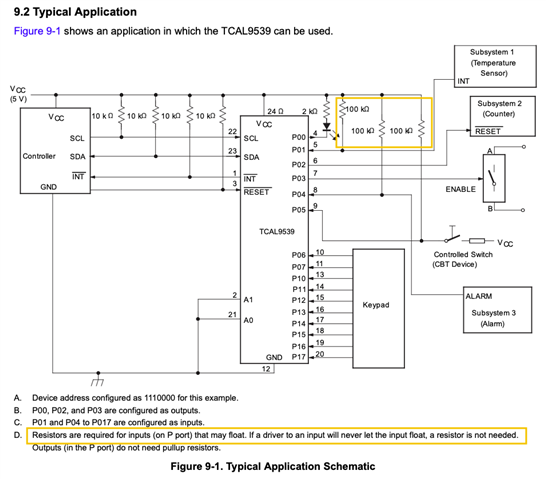
Why not configure the internal 100kΩ pull-up resistors that the TCAL9539 has instead of having to include them on the circuit?
If that is the case, then it would be better for me to use a TCA9539 instead, right?
Thank you!


