This thread has been locked.

If you have a related question, please click the "Ask a related question" button in the top right corner. The newly created question will be automatically linked to this question.

TCAN4550-Q1: CCCR.INT change conditions

Part Number: TCAN4550-Q1
Other Parts Discussed in Thread: TCAN4550

Tool/software:

Hello team,

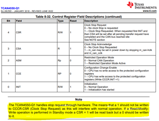
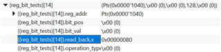
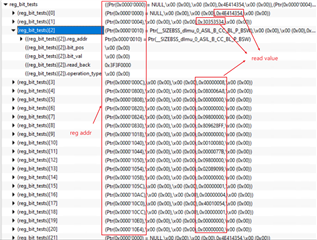
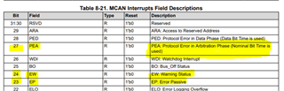
According to the datasheet, when MODE_SEL switch from standby to normal, the CCCR.INT should be written to 0 automatically, but it is found the related register is still 1 in the actual development, so customer want to know is there any other conditions to change the bit?

Thanks!

Regards,

Daniel Wang

  • Hi Daniel,

    This has not been my observation.  Can they provide more information to go with this claim such as the specific list of register write and read values for their configuration sequence?

    Regards,

    Jonathan

  • Hi Jonathan,

    We are using TCAN4550-Q1 with AutoSAR MCAL. We switched the CAN transceiver and controller states according to the demo program. The transceiver's initial state was configured to standby mode. We called the API CanTrcv_44_TCAN4x5x_SetOpMode to switch the state to CANTRCV_TRCVMODE_NORMAL, and then called the API Can_44_TCAN4x5x_SetControllerMode to switch the controller state to CAN_T_START. However, the call failed. The function that failed was Can_44_TCAN4x5x_MCAN_ResetInit. Upon checking the CCCR register, we found that an attempt was made to write 0x18, but the read value was 0x19.

    Transceiver initial state as standby mode 0x0800 register value

    Switching the transceiver state to normal mode 0x0800 register value:

    Initial state CCCR register value:

    Try to write 0x18:

    Read value:

    So, if we want to use the MCAL plugin based on AUTOSAR that you provided, are the above steps correct, and are there any other options that need to be configured?

    Thanks! 

    Regards,

    Zhengchao

  • Hi Zhengchao,

    I don't have any additional information about the MCAL driver than what is provided with it.  However I did have one concern with the following step:

    Try to write 0x18:

    The datasheet states that a "1" should not be written to the Clock Stop Request (CSR) bit 4 of the CCCR register.  If they are writing a value of 0x00000018 to the CCCR register 0x1018, then they are doing this which will halt the MCAN controller and will cause the INIT bit 0 to be set to 1 as well.  This bit will read back 1, but should always be 0 in all writes.

    Regards,

    Jonathan

  • Hi Jonathan,

    Thanks for your guidance.

    We successfully switched the controller state to CAN_T_START, but the attempt to send CAN messages failed. The register status is as follows:

    0x0800:

    Control Register 0x1018:

    Status 0x000C:

    Interrupts 0x0820:

    Protocol Status Register 0x1044:

    Error Counter Register 0x1040:

    Upon checking register 0x0820, we found that CANSLNT is set to 1. According to the datasheet, this bit should not be 1 in normal mode. Could you please explain under what circumstances this bit would be set to 1, and which other registers we can check to further analyze the issue?

    Additionally, upon checking the LEC bit in register 0x1044, the error is AckError. Could you please confirm if this error is caused by CANSLNT?

    Thanks! 

    Regards,

    Zhengchao

  • Hi Zhengchao,

    Upon checking register 0x0820, we found that CANSLNT is set to 1. According to the datasheet, this bit should not be 1 in normal mode. Could you please explain under what circumstances this bit would be set to 1, and which other registers we can check to further analyze the issue?

    Under normal CAN bus communication, it is assumed that the bus should have enough message activity on the bus to prevent an idle or recessive state for long periods of time.  There are several reasons for this including keeping the can controller clocks within tolerance of the other nodes so that the bits are correctly sampled, but also to help verify a node has not been disconnected from the bus which would be a fault condition.

    The CAN Silent (CANSLNT) bit will be set when CAN bus activity (recessive-to-dominant, or dominant-to-recessive transitions) are not detected for approximately 1 second.  The timer threshold may vary between devices and PVT conditions between 0.6s and 1.2s.  In lab testing conditions with a point-to-point test setup it is common to see the CANSLNT bit set due to infrequent CAN messages transmitted based on human commands and not as part of a fully functioning autonomous system. 

    Additionally, upon checking the LEC bit in register 0x1044, the error is AckError. Could you please confirm if this error is caused by CANSLNT?

    Having the CANSLNT bit set will not impact the ability of the device to transmit or receive CAN messages and this is just a notification that there has been no CAN activity detected for longer than 1s.

    An AckError occurs when a message is transmitted on the CAN bus but does not receive an Acknowledge (ACK) response from another CAN node on the bus, or an error frame.  So when a message is transmitted into an empty bus, it will not receive an ACK and it will consider this a transmit error because it was not successfully received by another node and acknowledged, and it will usually automatically try to re-transmit this message until there is another node that provides the ACK response.

    Regards,

    Jonathan

  • Hi Jonathan,

    So, can I understand that the current register status is normal, and the AckError is caused by the response from external nodes? If I want to verify whether the TCAN4550 has successfully transmitted, I can use an oscilloscope to measure the signal.

    Thanks! 

    Regards,

    Zhengchao

  • Hi Zhengchao,

    Yes, AckErrors are the result of a transmitted message Not receiving an acknowledge pulse from another node on the bus.  This also means that there were no other Error Flags thrown on the message either. 

    But basically this means that the message was transmitted on a bus where there was no other nodes capable of receiving a message and acknowledging it did contain protocol errors that would deserve an error flag.

    These are common in a lab setting when there is not a lot of functioning CAN nodes, or when a bus is just starting up and the first node transmits a message before any other nodes are read to communicate.

    Yes, you should always be able to use a scope to verify a message was transmitted.

    Regards,

    Jonathan

  • Hello Jonathan,

    We used an oscilloscope to measure CAN_H and CAN_L, and the signals from the TCAN4550 are as follows:

    However, I did not receive any information using CANoe. Therefore, I would like you to confirm if there is an issue with the register values. The register information read is as follows (only some registers):

    Additionally, we are using the EB tresos plugin provided by you. I would like you to check the configuration information to see if there is any issue with my configuration:

    1 CAN controller:

    2 CAN Trcv: 

    Many thanks!

    Regards,

    Zhengchao

  • Hi Zhengchao,

    I apologize for the delay.  Thank you for your patience while I was out of the office last week.

    The MCAN Interrupt Register has bits 27, 24, and 23 set which are for PEA (Protocol Error in the Arbitration Phase, Nominal Bit Time is used), EW (Error Warning Status, and EP, Error Passive.  This indicates a likely issue with the bit timing or clock that is resulting in an incorrect bit timing configuration causing the CAN messages to generate errors with other devices that are configured correctly.

    The Error Counter Register (0x1040) does also show CEL and TEC errors are being accumulated.

    The Modes of Operation and Pin Configuration register 0x0800 has the CLK_REF bit set to 1 (bit 27) which tells the device the crystal frequency is 40MHz,  but your configuration seems to indicate a crystal frequency of 20Mhz.

    You didn't provide the actual Nominal Bit Timing and Prescaler register (0x101C) value, but your time quanta configuration appears correct for 500kbps when using a 20MHz crystal. 

    Verify the value of register 0x101C matches your desired configuration.  Also measure the bit period on a scope to make sure it has the correct width for a 500kbps bit which should be 2us.

    The TX Buffer Configuration Register (0x10CC) does show there is a TX message pending transmission that has not been successful, so this indicates a likely bit timing configuration preventing any other CAN nodes such as the CANoe from recognizing the bit timing as correct.  This would explain the bit errors, the lack of acknowledgement, and the TX message pending status.

    Verify the bit timing is compatible with both the TCAN4550-Q1 and the CANoe configurations and try again.

    Regards,

    Jonathan