This thread has been locked.

If you have a related question, please click the "Ask a related question" button in the top right corner. The newly created question will be automatically linked to this question.

DS160PR410: PCIE can't link

Part Number: DS160PR410

Tool/software:

Hi,

We have occur PCIE can't link issue.

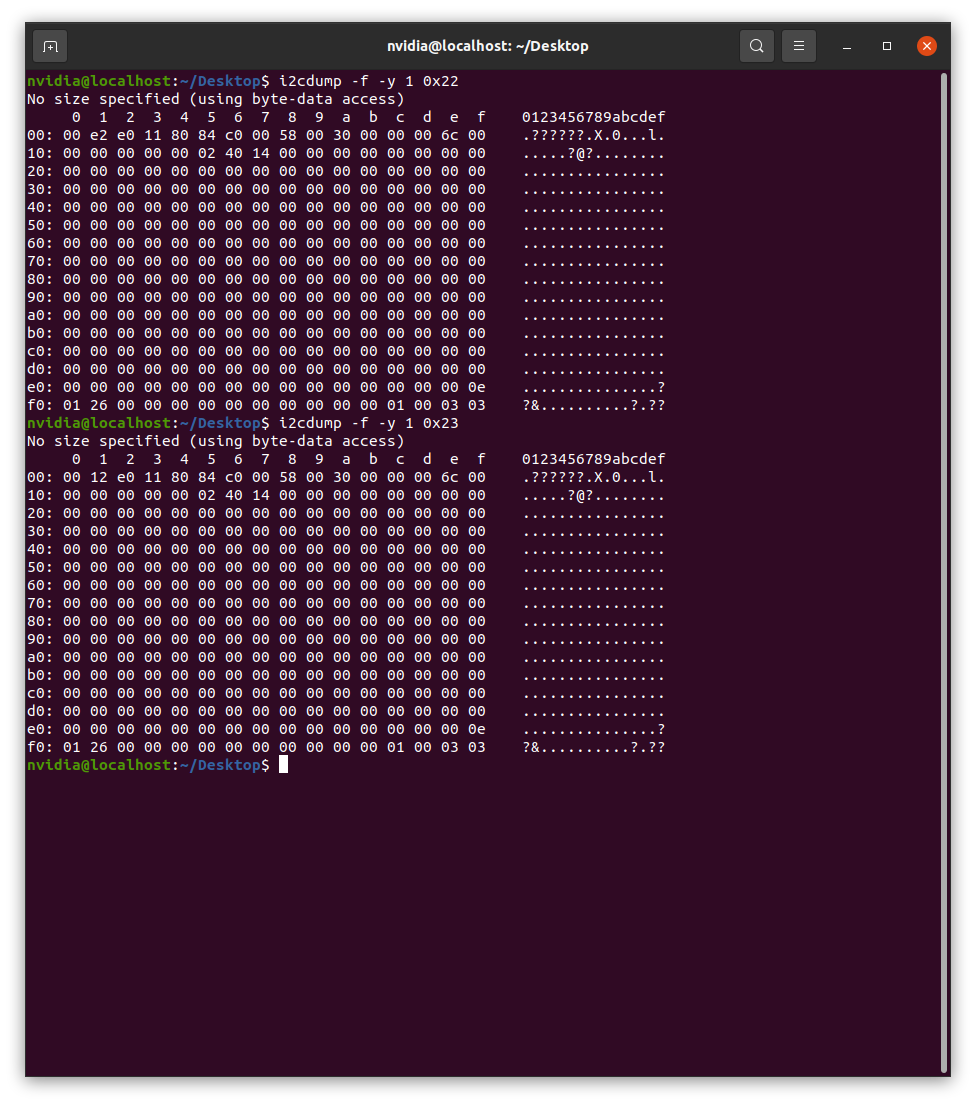
we can link in I2C mode but the signal is weak. And can't link in HW pinstrap mode. Would you please help us check the schematic? 

Or we need provide the eye diagram for review? thanks!

DS160PR410(1).pdf

Jeff

  • Hi Jeff,

    Thank you for reaching out regarding this issue. An engineer has been assigned to this thread and will get back to you in the next 24 hours.

    Best,
    David

  • Hi David,

    Got it, please help this urgent issue. thanks!

  • Hi Jeff,

    we can link in I2C mode but the signal is weak. And can't link in HW pinstrap mode.

    If I ignore the comments, the schematic as written has the device operated in Pin Mode with an EQ setting of 0 (-0.8 dB at 8 GHz), a VOD setting of -1.5 dB, and Gain setting of +3.5 dB. I think this is a confusing configuration because the device is not applying any equalization, it is actually reducing the frequency levels of the signal. The negative VOD setting and positive Gain setting seem to contradict each other. So I am confused by the intention of this pin mode configuration and would not expect that it could improve the signal quality.

    The comments seem to switch the device into I2C mode, however I don't have further information.

    My questions:

    • What device settings did the customer program in I2C mode? I expect that to produce different results from the pin mode, they have programmed it with other EQ settings for example.
    • What was the customer's motivation for using the redriver in this application? Do they know the total link loss and how much reach extension the redriver is expected to provide?

    Best,

    Evan Su

  • Hi Evan,

    Today, we conducted tests on the M.2 Port using an SI oscilloscope. However, we found that the settings adjusted via I2C in SMB_Slave mode differed from those adjusted via resistors in Pin mode during actual testing.

    During the PCIe Preset test, the settings adjusted via I2C passed, but the settings adjusted via resistors in Pin mode failed, showing clear inconsistencies in the test results. We have verified that both configurations were set to the same values as specified in the datasheet. The test report is attached.

    Could you please help us investigate why this discrepancy is occurring?

    Pin mode resistor settings:

    • VOD: Float
    • Gain: 59K
    • EQ1_ADDR: 13K (L1)
    • EQ0_ADDR: Float (L2)
    • EN_SMB: 1K
    • RX_DET: Float
    • READ_EN_N: Float

    I2C mode register settings:

    Both DS160PR410 chips are configured with the same register settings.

    I2C_mode_PreSet_Test.pdfPin_mode_PreSet_Test.pdf

  • Hi Jeff,

    The pin mode settings you posted here (different from the schematic) lead to this equalization behavior from the device:

    • VOD: float = L2 --> 0 dB
    • Gain: 59K = L3 --> 3.5 dB
    • EQ1 = L1 and EQ0 = L2 --> EQ Index 6

    I don't recognize the information in the I2C register dumps and am unable to compare the I2C settings to the pin mode settings. Can the customer tell us the exact register programming sequences they used to program the devices?

    Best,

    Evan Su

  • Hi Evan,

    We can pass the test via bewow setting from I2C mode.

    This is our final desired configuration, and we hope to use HW pin strap mode. Could you please help confirm what adjustments are needed on the hardware circuit?
    • Writing 0x03 to register 0xFF enables broadcast mode to all channels.
    • Writing 0x01 to register 0xFC selects Channel 0 for configuration.
    • Writing 0x80 to register 0x04 sets DC Gain to +3.5 dB and disables EQ bypass.
    • Writing 0xC0 to register 0x06 sets VOD Level to 0 dB.
    • Writing 0x1A to register 0x03, according to the CTLE Index Table, switches to index 6.

    Thanks!

    Jeff

  • Hi Evan,

    I've check for index 6 and DC Gain to +3.5 dB in pin mode, please help us double check it correct. thanks!

    Gain: L3, 59 kΩ to GND.

    VOD: L2, Floating.

    EQ1_ADDR1:L1, 13 kΩ to GND

    EQ0_ADDR0: L2, Floating.

    EN_SMB: L0, 1 kΩ to GND

    ALL_DONE_N: Floating.

  • Hi Evan,

    We found the Programming Guide table 10 seems something wrong, it mentioned 0x80 set DC gain to 3.5dB, but as table 24 it should be 0x20?

    So we set 0x80 seems actully set DC gain to 0dB?

    Since I2C mode set 0x80 is pass, we will tried to set DC gain to 0 to check pin mode can also pass the test as I2C mode. thanks!

    https://www.ti.com/lit/ug/snlu255/snlu255.pdf?ts=1744704723586&ref_url=https%253A%252F%252Fwww.ti.com%252Fproduct%252FDS160PR410%253FkeyMatch%253DDS160PR410%2526tisearch%253Duniversal_search%2526usecase%253DGPN-ALT

  • Hi Jeff,

    I believe the register values listed in step 3 of table 10 are incorrect by mistake. Accurate programming should follow the register and field descriptions in Table 24. Following Table 24, the correct overall register value (ignoring the value mask) to configure the DC Gain as 0 dB while keeping the other settings at recommended levels would be 0b0001_0110 = 0x16, which is the default/reset value.

    So we set 0x80 seems actully set DC gain to 0dB?

    Not sure what mask value the customer may have used, but I would expect that the DC gain was not changed to 3.5 dB from the original 0 dB, instead some of the reserved settings may have been modified (which is not recommended). Since 0 dB is the default setting in I2C mode, if this produces passing results, the 0x04 channel register can be left alone without any programming changes.

    Since I2C mode set 0x80 is pass, we will tried to set DC gain to 0 to check pin mode can also pass the test as I2C mode. thanks!

    Yes, that is a good idea. It sounds like the previous pin mode configuration of 3.5 dB DC Gain may have been too high (the output driver is running at a very high amplitude and there may be some issues with nonlinearity or noise amplification) for accident and the 0 dB default setting tried by accident in the I2C mode testing may be more appropriate. With the correction of the DC gain setting in pin mode to 0 dB I expect the results should be the same as in the I2C tests, let us know how it goes.

    Best,

    Evan Su