This thread has been locked.

If you have a related question, please click the "Ask a related question" button in the top right corner. The newly created question will be automatically linked to this question.

TPS565201: Output capacitance and load capacitance

Part Number: TPS565201

Tool/software:

Hi,

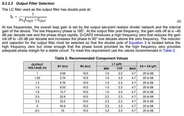
I'm planning to use TPS565201 in my design to have an output voltage of 3.3V. In the datasheet, the recommended inductor value is 2.2 uH, and the the recommended output capacitance value is between 20uF - 68 uF. 

The load exists on the same board, and it has a value of 200 - 300 uF. A power layer is used, so the inductance and resistance between the buck converter's output and the load assumed to be low.

I'm wondering if the load capacitance affect the output capacitance of the buck converter?

Best regards, Ali

  • Hi,

    of course the total output cap is combination of Converter Cout and the cap on point of load.  if the recommended Cout is 68uF, you may place 10uF close to TPS565201 and 47uF close to point of load. 

    you may have to add Cff cap on RFBT if much larger Cout used than recommended value on data sheet   

  • Thanks,

    I think we have to use much larger Cout. I see that in many of TI buck converters, a simple equation is given to calculate the crossover frequency like " Fx = (some number)/(Vout * Cout) ", is there any equation that could be used to calculate it for the TPS565201 device?

  • Hi

    Pls refer to the section 8.2.2.2 for L/Cout selection.  the Cff can be used to boost phase margin if much bigger Cout is used.