This thread has been locked.

If you have a related question, please click the "Ask a related question" button in the top right corner. The newly created question will be automatically linked to this question.

DS90CR286A: DS90CR286A to DVI1.0

Part Number: DS90CR286A
Other Parts Discussed in Thread: TFP410,

Tool/software:

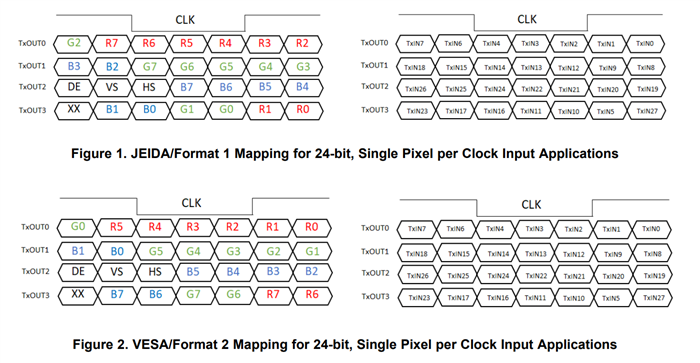
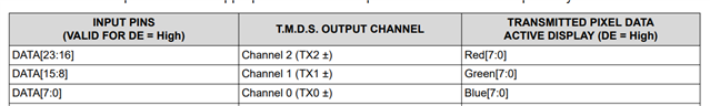
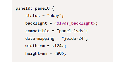
I have an NXP iMX9352 with integrated LVDS phy. The datasheet says it supports common display LVDS receivers which I assume are 24 bit VESA or JEIDA mapping.

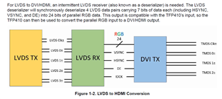
I am using the DS90CR286A to deserialize and the TFP410 to finally output TMDS lanes.

If the LVDS output already complies to a standard, and the TFP410 is my "RGB Receiver" then

Do I connect RX0-23 VSYC, HSYNC, and DE up to TFP410 input 0-26. in a 1:1 straight connection leaving RXout27 disconnected

OR

Do I need to connect RXout 27 to TFP410 input 23 to get R0/R6 bit, and leave RXout23 disconnected

The DS90CR286A is confusing me with the color mapping calling RXout23 as the general purpose bit.

Is the mapping already taken care of in the host processor output, or do I need to take care of it in Hardware traces between the deserializer and TFP410?

The app note for LVDS to HDMI is too vague.

  • Hi Mike,

    Welcome to the E2E forum!

    TxIN23/RxOUT23 is called the general purpose bit but for most cases it is not used since 24-bit RGB video contains total 27 bits (24-bit video + 3 sync signals) and the LVDS frame has 28 slots for data.

    Do I need to connect RXout 27 to TFP410 input 23 to get R0/R6 bit, and leave RXout23 disconnected

    For LSBs on RxIN3 (JEIDA), RxOUT27 will be connected to TFP410 input 16. For MSBs on RxIN3 (VESA), RxOUT27 will be connected to TFP410 input 22. You can leave RxOUT23 disconnected if you prefer.

    The TFP410 expects the following input for R, G, and B components

    Is the mapping already taken care of in the host processor output, or do I need to take care of it in Hardware traces between the deserializer and TFP410?

    You will need to take care of the traces between the CR286 and the TFP410 depending on the LVDS mapping scheme. If the mapping scheme is incorrect it will result in incorrect colors received on the display.

    Best,

    Jack

  • I am aware of the standards...

    Just for clarification the TI app note "How to Bridge LVDS/OLDI to HDMI/DVI" shows the following:

    Very clear and specific <sarcasm>

    So if my LVDS phy already complies with the VESA standard, and I then reMAP with connections in Hardware, will it undo the mapping.

    I think you answered the question though, no matter what the TFP410 is expecting RED(7:0) on 23:16 etc... So I have to remap everything in the CMOS traces on the board.

    (Unless there is a way to pre-map the LVDS video controller and phy output... but this is a provided linux driver and not sure I want to write my own driver for this)

  • Hi Mike,

    So if my LVDS phy already complies with the VESA standard, and I then reMAP with connections in Hardware, will it undo the mapping.

    Yes, you can undo the mapping if you do not follow the correct hardware connections.

    (Unless there is a way to pre-map the LVDS video controller and phy output... but this is a provided linux driver and not sure I want to write my own driver for this)

    From a quick search, I found a thread on the NXP forums where there is an option for data format. I'm not an i.MX93 expert so double check the available documentation for your processor, kernel, driver, etc. I haven't seen an LVDS TX that only supports one data format.

    Best,

    Jack

  • Thanks, I didn't dig into the forums...

    That gives me a place to search.

    The NXP data sheet is very specific on what it supports <more sarcasm>

    So, it isn't VESA or JEIDA, it only supports "relevant" devices. :-)