This thread has been locked.

If you have a related question, please click the "Ask a related question" button in the top right corner. The newly created question will be automatically linked to this question.

TCAN4550-Q1: TCAN4550EVM Enabling internal loopback mode

Part Number: TCAN4550-Q1
Other Parts Discussed in Thread: TCAN4550EVM, TCAN4550

Tool/software:

Hello,

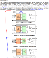
I am playing around with the TCAN4550EVM board, and have gotten SPI communication to work, where I can read and write the registers on the TCAN4550. However, I have been trying to put the chip in loopback mode so I can start pulling from the RX FIFO of the chip and processing messages, but have not succeeded in doing so. I just wanted to confirm my configuration and make sure I am not missing anything.

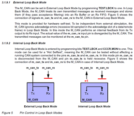
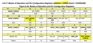
I am using the supplied software to configure the chip, including MRAM. Before the chip is put into normal mode I also configure the test register (0x1010) to enable loopback mode, and configure the cccr register (0x1018) to enable the MON bit, to disable external signals and only have internal loopback. 

The TCAN4550 is put into normal mode. 

The TCAN4550 is put into test mode using TCAN4x5x_Device_EnableTestMode(TCAN4x5x_DEVICE_TEST_MODE_CONTROLLER), and ensuring that the function returns true. 

I then use the supplied software, lines 92-106 in main.c to write to the TX buffer, and line 129 to transmit the buffer. I know that up to this step it is working, because when not in loopback mode I get the message on the CAN bus. I also have verified that the correct data is getting written to the TX buffer. 

However when trying to read the RX FIFO using lines 136-152 in main.c, the rx buffer is empty. 

I have looked at the interrupts regsiter, and CANSLNT bit is set. Also in the mcan interrupts the TSW bit is set. Also in the SPI interrupts register bit 3, Internal_access_active, is high. 

Please let me know if there is anything that I am doing wrong here. I'd really like to get internal or external loopback working on this chip. 

Thanks, 

Bennett

  • Hi Bennett,

    The TCAN4550 is a combination of the MCAN CAN FD Controller and a CAN transceiver.  System level compliance tests have MCAN specific tests, and Transceiver specific tests and so there is a Test Mode that allows the TX and TX signal to be accessed through the GPIO1 and GPO2 pins. What can also be confusing is that the MCAN controller also has some "test mode" capabilities in the form of loopback testing that does not require the device level test mode functions that re-route out the internal RX and TX signals to the GPIO pins.

    The TCAN4x5x_Device_EnableTestMode(TCAN4x5x_DEVICE_TEST_MODE_CONTROLLER) function will disconnect the MCAN controller from the transceiver and will be using the controller test mode as shown in figure 8-11 in the following figure.  The two test modes grouped by the red line allow the MCAN and transceiver test modes.  Neither figure 8-10 or 8-11 that are enabled with this function are what you want for doing a loopback test.  Instead, I do not think you  want to use this TCAN4x5x_Device_EnableTestMode  function and instead just configure the appropriate MCAN registers.

    Instead the MCAN controller IP also has a "test mode" that allows or internal or external loopback testing and the customer will want to use one of these two configuration mode instead.  They are only configured through the MCAN registers and do not require the pin-based test mode for the two red configurations.

    First, the TEST bit in the Control Register needs to be set to "1" in order allow access to the TEST register bits such as LBCK.  Please make sure that 0x1018[7] = 1.

    The MCAN controller has two forms of Loop Back, and Internal and and External Mode.  The LBCK bit in the Test Register needs to be set to "1" for both types of Loop Back.  Please make sure that 0x1010[4] =1. 

    If Internal Loop Back is used, the transmitter needs to be disabled and this is done by also setting the MON bit in the Control Register to "1" to enable the Bus Monitoring Mode.  Please make sure that 0x1018[5] = 1 if Internal Loop Back is desired.

    The following image is taken from the Bosch M_CAN User's Manual (Link) and is a good illustration of how the device is configured for Loop Back. 

    I have looked at the interrupts regsiter, and CANSLNT bit is set. Also in the mcan interrupts the TSW bit is set. Also in the SPI interrupts register bit 3, Internal_access_active, is high. 

    The CANSLNT bit is likely getting set because you have disconnected the CAN transceiver from the controller and it does not see any bit activity on the RX signal connected to the GPO2 pin in Controller Test Mode for longer than 1s. 

    The TSW is just an indicator that the timestamp counter has wrapped around if you were keeping track of timestamps on your CAN messages.

    The Internal Access Active bit is just an indicator there is internal activity, and is not an indicator of any error.

    I would suggest trying to remove the TCAN4x5x_Device_EnableTestMode function and try again.

    Also here is just a bit of additional information that may help you understand the registers in this device.  The MCAN controller IP was developed by Bosch and used as-is ini the TCAN4550 with one exception.  Every register address has had an offset of 0x1000 added to it.  Otherwise all of the information in the previously linked manual is applicable.  You will simply need to interpret the register addresses in the MCAN User's Manual as having an additional 0x1000 offset.  For example, the MCAN Control register has address 0x18 in the MCAN User's Manual and an actual address in the TCAN4550 of 0x1018.

    All other registers in the TCAN4550 that are not related to the MCAN have an address less than 0x1000. 

    Registers related to the SPI Interface read/write FIFO are in the range of 0x0000 to 0x002F.  These registers only require the SPI clock domain to be active to return a value.

    Registers related to the hardware and digital core features that are not related to MCAN have an address in the range 0x0800 to 0x08FF.  These registers, along with the MCAN registers, require both the SPI clock and High Speed OSC clock to be active and stable for read/write access.

    The TCAN4x5x_Device_EnableTestMode function is controlling bits in Register 0x0800 which is a non-MCAN register related to routing our the internal RX and TX signals.

    I hope this information helps clarify things.

    Regards,

    Jonathan