


Part Number: THVD2450
Other Parts Discussed in Thread: THVD1510
Tool/software:
Hi TI experts
I have a differential signal that is transmitting into the bus pins (A and B) of THV2450 and they are +- 14V. I want to select a TVS diode for the circuitry. Do you have any recommended TVS diode? Would SMAJ14CA be sufficient to protect the device and the lines from transcient and surge?
Also the datasheet states that the receiver pins has a fail-safe operation feature and
"The receivers are fail-safe to invalid bus states caused by the following:
• Open bus conditions, such as a disconnected connector
• Shorted bus conditions, such as cable damage shorting the twisted-pair together
• Idle bus conditions that occur when no driver on the bus is actively driving
In any of these cases, the receiver outputs a fail-safe logic high state if the input amplitude stays for longer than
tD(OFS) at less than |VTH_FSH|."
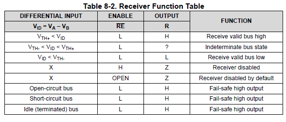
Do I still need a pullup resistor for when the output is "?"
Appreciate your patience helping me with these
Best Regards
Ena

