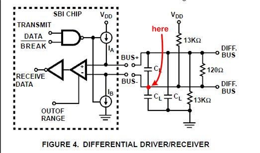
Can you help clarify why the A,B outputs from the SN65176 waveforms below are asymmetric? The circuit below shows external termination network (13k pullups and 120 parallel)


Can you help clarify why the A,B outputs from the SN65176 waveforms below are asymmetric? The circuit below shows external termination network (13k pullups and 120 parallel)