This thread has been locked.

If you have a related question, please click the "Ask a related question" button in the top right corner. The newly created question will be automatically linked to this question.

DP83822I: Need help with an example circuit for RMII 100FX mode

Part Number: DP83822I
Other Parts Discussed in Thread: DP83822EVM

Tool/software:

Hello there. 

I have read through you datasheet and I find it difficult to follow as to how to configure this device in the mode that I want. 

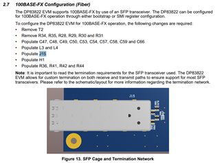
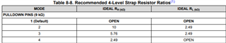
Is there a reference circuity somewhere that includes all connections including the MAC -> PHY connections, 4-level bootstrap configuration, and PHY-> Fiber connections? 

I understand the general connections that all RMII's have to MAC's, I am just unclear how to connect your specific device. 

If there does exist a reference design somewhere please link it to me, thank you!!

  • Hi Silas,

    We have the DP83822EVM that can be a good reference for implementing strap options. In the EVM User's guide, Figure 17 shows how the LED pin straps can be handled, and Figure 19 shows how the other strap options can be handled.

    This EVM does not have a MAC included on the board. You can think of the J14 and J13 headers as connecting to a MAC externally.

    This EVM does not come standard with a fiber connector. You can follow the instructions in section 2.7 of the User's guide to bring up a fiber connection in this design.

    Best,

    Shane

  • Thanks for replying! 

    I think I roughly understand how to connect it up, but I am still not clear on how to configure the pull up and pull down's in figure 19 to achieve the correct configuration for RMII, 100FX operation.

  • To set 100FX on the MDI side, you should strap the COL signal (pin 29) to Mode 2 or Mode 3. You can specify full or half duplex by strapping LED_0 to Mode 4 or Mode 1 respectively:

    The PU/PD resistor combinations for each mode setting on COL and LED_0 is shown in the table circled below:

    To set RMII on the MII side, you should strap the RX_DV signal (pin 26) to Mode 3 (RMII 25MHz ref clock) or Mode 4 (RMII 50MHz ref clock).

    The PU/PD resistor combination for each mode setting on RX_DV is shown in the table below:

    I hope this helps, let me know if you have any questions.

    Best,

    Shane