This thread has been locked.

If you have a related question, please click the "Ask a related question" button in the top right corner. The newly created question will be automatically linked to this question.

DS90UB960-Q1EVM: Set up the Deserdes 960 error during runing in EVM board.

Part Number: DS90UB960-Q1EVM
Other Parts Discussed in Thread: TSER953, DS90UB953-Q1, DS90UB960-Q1, TDES960

Tool/software:

i try to set up new camera with uB960 and UB953. Here is the status below:
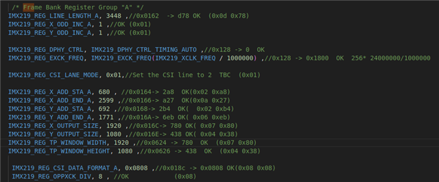
1. Sensor have correct config. and the sensor register "FrameCnt" changed after the register be read out. So video have be send out
2. read the GENERAL_STATUS register. The val is 0x45. It mean that the bit RX_LOCK_DETECT/HS_PLL_LOCK/LINK_DET was 1. this indicator the physical and config of 953 is correct implement

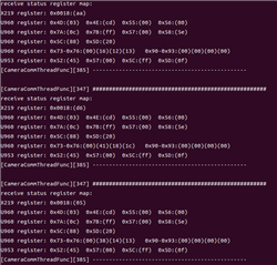
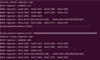
3. Read the CSI_RX_STS from 960. It show that the LENGTH_ERR and CKSUM_ERR. and by the way the Frame counter is 0 in 960 register and Image Line counter is wrong

Can you share me that the problem. and how i need to deal with this problem. thx

  • Hi Meng,

    Can you share the following register values? This will help me pinpoint which section of the signal chain may be introducing errors.

    • On UB960: 0x4d, 0x4e, 0x55, 0x56, 0x7a, 0x7b
      • Please confirm the correct FPD port is selected in register 0x4c and the correct CSI port is selected in register 0x32 before reading these registers.
    • On UB953: 0x57, 0x5c, 0x5d

    Best,

    Lucas

  • Hello Lucas Wolter:
    read register though i2c. here is the register below
    For
    960:
    0x4D(0x03) 0x4E(0x04)
    0x55(0x00) 0x56(0x00)
    0x7A(0x00) 0x7B(0x00)
    0x57(0x00) 0x58(0x07)
    0x5c(0xff) 0x5D(0x0f)
    0x73-0x76(0x00 0x00 0x00 0x00)
    0x90&0x91(0x00 0x00)

    0x4C(0x01) 0x32(0x01)
    For 953:
    0x52(0x45) 0x57(0x00) 0x5C(0xff) 0x5D(0x0f)

    I was setting the register as below table. maybe the setting for Rx is not correct. Thanks very much

    static
    const u_int8_t Ds90up960_tbl[100] =
    {
    0x01, 0x02 ,
    0x0C, 0x00 ,
    0x1f, 0x00 ,// CSI0 00: 1.472 - 1.664 Gbps serial rate

    0x32, 0x01 ,
    0x33, (0x42) , // CSI_EN & CSI0 2L 42 Read -> 43
    0x4c, 0x01 , // RX_PORT0 ub960_rxport_select(0)
    0x58, 0x06 , // 0x58 (7)(6)!
    0x4c, 0x01 , // RX_PORT0 ub960_rxport_select(0)
    0x6D, 0x00 , // 0x6d (3)(0)!
    0x4c, 0x01 , // RX_PORT0 ub960_rxport_select(0)
    0x7C, 0x00 , // 0x7c (3)(0)!
    0x4c, 0x01 , // RX_PORT0 ub960_rxport_select(0)
    0xd8, 0x07 , // 0xd8 (07)!
    0x4c, 0x01 , // RX_PORT0 ub960_rxport_select(0)
    0xd9, 0x7F , // 0xd9 (7f)!
    0x4c, 0x01 , // RX_PORT0 ub960_rxport_select(0)
    0x58, (64) , //0x58 (64)(64)! 0x46?????
    0x4c, 0x01 , // RX_PORT0 ub960_rxport_select(0)
    0x5c, (88),
    0x58, (0x9e) , // enable I2C Pass-Through All Transactions
    0x42, (0x71) ,
    0x41, (0xA9) ,

    0xb0, (0x04),
    0xb1, (0x08),
    0xb2, (0x08),
    0xb1, (0x09),
    0xb2, (0x08),
    0x4c, 0x01 , // RX_PORT0 ub960_rxport_select(0)
    0xd5, (0xE0),
    0xd2, (4),
    0xd4, (0),
    0x0c, (1),
    0x01, (0x01),

    0xb1, (8),
    0xb1, (9),
    0x4c, (0x12),//0x12
    0x4c, (0x24),//0x24
    0x4c, (0x38),//0x38
    0x4c, (1),//0x01
    0x5d, (0x20),//0x20
    0x65, (0x94),//0x94

    0xFF,0xFF
    };
  • Hi Meng,

    Thank you for sharing your register values and register write sequence. I see the following in your register dump:

    • Values in 960 registers 0x58, 0x5c, and 0x5d don't quite make sense to me.
      • 0x58 indicates back channel is disabled, however this does not line up with the settings programmed to 0x58 in your register write sequence (0x58=0x40).
      • 0x5c indicates that the SER alias ID is 0xff which doesn't seem correct. 0x5c=0x58 is written in your register write sequence.
      • 0x5d indicates that the target ID is 0x0f which doesn't seem correct. 0x5d=0x20 is written in your register write sequence.
    • 953 registers 0x5c and 0x5d indicate several CSI errors detected on data transmitted by the camera.
    • All other error registers indicate no errors. 960 CSI registers do not detect any data being received.

    Based on these findings, it seems likely that the 953 is not receiving data properly from your camera.

    • Can you confirm that the camera is connected properly and capturing/transmitting data correctly?
    • Can you share your register write sequence for the 953 for review?
    • Can you share your 953 schematic for review?

    Best,

    Lucas

  • Hello Lucas:
    for 960. I update the 0x58 & 0x5C register and update the Device ID. Here is the Register read form UB960 below:

    0x4D(0x03) 0x4E(0x04)
    0x55(0x00) 0x56(0x00)
    0x7A(0x00) 0x7B(0x00)
    0x57(0x00) 0x58(0x5E)
    0x5c(0x88) 0x5D(0x20)
    0x73-0x76(0x00 0x00 0x00 0x00)
    0x90&0x91(0x00 0x00)

    for 953. Here is the register read below:
    0x52(0x45) 0x57(0x00) 0x5C(0xff) 0x5D(0x03)

    here is the register write table config for UB953

    static const u_int8_t Ds90up953_tbl[50] =
    {
    0x0b,0x13,//OK
    0x0c,0x26,//OK
    0x02,0x52,//OK
    0x0d,0x02,//0x02
    0x0e,0x2D,//0x2D
    0x06,0x41,//OK
    0x07,0x28,//OK

    0xFF,0xFF,
    };

    and here is the UB953 schematic below:


    By the way. The sensor Frame Count can be read. and the Count will be change each time i read the register.

    thanks very much

  • Here is the Mode setting and REF Clock below:

  • Hello, 

    Due to US public holiday on Friday 4/18/25, support will resume on Monday. Thank you for your patience. 

    Regards, 

    Logan

  • Hi Meng,

    Your register values for 0x58, 05c, and 0x5d on the 960 now make more sense to me. The issue appears to be occurring at the CSI-2 input on the 953. The 953 is detecting various CSI-2 errors (see registers 0x5c and 0x5d). All other error/status registers you have shared with me do not indicate any issue.

    I reviewed your 953 register write sequence and schematic and have the following feedback.

    • Are you using DS90UB953-Q1 or TSER953? For my review, I am assuming you are using DS90UB953 even though your schematic labels the device as TSER953.
    • How many CSI-2 data lanes are used to transmit data from the camera to the 953? Your schematic shows connections on all 4 data lanes. However, writing 0x02=0x52 configures the 953 for 2 data lanes only.
    • SDA and SCL include 4.7k pullups to 3.3V, however the strap on IDX selects 1.8V I2C voltage.
    • Typically it is recommended to use a 10uF decoupling cap on PDB pin.
    • I don't see which components are connected to DOUT+/- pins. Can you share relevant AC coupling and PoC networks (if power over coax is used)?

    Best,

    Lucas

  • here is the poc for 953 

  • hello lucas wolter:

    sorry. type a wrong name . i am using for TSER953. and for this project i am using two line for receive the CSI image signal.

    the connect to DOUT pin is show in pevious picture. and the Power over coax is used. thanks very much

  • Hello Lucas Wolter:

    I have update the table for 953. Here is the update table below:

    static const u_int8_t Ds90up953_tbl[50] =
    {
    0x0b,0x13,//OK
    0x0c,0x26,//OK
    0x02,0x53,//OK I2c SDL/SDA -> 1.8V
    0x0d,0x02,//NOK->0x02 R00
    0x0e,0x2D,//NOK->0x2D
    0x06,0x41,//OK
    0x07,0x28,//OK

    0xFF,0xFF,
    };

    after config the table. below register was read out. And i check the U960 register: 0x73-0x76:(04)(3a)(07)(80). This is mean that 960 can read the frame information with width:0x43a = 1080 and line 0x780 = 1920.
    but the register 0x90&0x91 show that CSI0_FRAME_COUNT remain will 0.

    receive status register map:
    X219 register: 0x0018:(3d)
    U960 register: 0x4D:(13)  0x4E:(45)  0x55:(00)  0x56:(00)
    U960 register: 0x7A:(00)  0x7B:(00)  0x57:(00)  0x58:(5e)
    U960 register: 0x5C:(88)  0x5D:(20)
    U960 register: 0x73-0x76:(04)(3a)(07)(80)   0x91-0x92:(00)(00)
    U953 register: 0x52:(45)  0x57:(00)  0x5C:(00)  0x5D:(00)

  • Hi Meng,

    It looks like changing the I2C voltage setting to 1.8V fixed CSI-2 errors at the 953 which is a good sign.

    A few clarifying questions:

    • I understand you're using TSER953. Are you using TDES960 or DS90UB960-Q1? Are you using an EVM for the 960 or a custom board?
    • Is your camera only transmitting data on 2 CSI-2 lanes? Register 0x02 on the 953 is programmed such that the Ser only receives data on 2 lanes.

    I reviewed your latest register values and see the following.

    • 0x4D indicates lock status changed but the 960 currently has lock.
    • 0x4E indicates line length and line count changed.
      • I'm wondering if these are extraneous errors. If you read register 0x4D-0x4E multiple times over multiple powerups, do you consistently see the same values?
    • 0x73-0x76 indicate that the last received CSI-2 frame had 1082 lines and 1920 bytes per line.
      • Does this match your expectation? Is this the resolution of your camera?
    • 0x7A and 0x7B indicate no CSI-2 errors detected at the 960.
    • It looks like you only read register 0x91 and 0x92 which do not give a full picture of the frame count.
      • 0x91 is the LSB of frame count and 0x92 is the MSB of error frame count.
      • Can you read all of 0x90-0x93 a few seconds after powerup?
      • Note that these register clear on read, so reading multiple times will result in varying values.

    Additionally I reviewed your PoC network. I see the following differences from the recommended network shown in the datasheet.

    • Ferrite bead selection has different impedance profile than TI recommendation: 550ohm @ 1GHz while TI recommends 1.5kOhm @ 1GHz.
    • Third ferrite bead is replaced with a 0ohm.
    • C14 decoupling cap is 4.7uF while TI recommends using at least 10uF.

    Generally, we recommend performing simulations if the recommended PoC network isn't followed exactly. However I believe it's unlikely that the PoC network could be causing CSI-2 issues in this case.

    Best,

    Lucas

  • hello Lucas Wolter:

    I using an EVM for the 960 called "fustion board" . and chip in fusion board was "TDES960"

    Here is the  Sensor "Imx219" line register. I choose the line number to 2line

    /* imx219_configure_lanes start */
    IMX219_REG_CSI_LANE_MODE, 0x01,//Set the CSI line to 2 TBC (0x01)
    /* imx219_configure_lanes start */


    I read the register period. It seems that the frame H-total and V-total count error. It changed every time read  the register. and the 0x90-0x93 is 0 all the time. Seems that the 960 have receive video but some error appear there. 

  • Hi Meng,

    I understand you are using TDES960 and 2 CSI-2 lanes, thank you for the clarification.

    I reviewed your latest register values. These values are significantly different from the last time you read register values, so I'm wondering if you changed anything in your setup since last time?

    I see the following errors are flagged:

    • CSI-2 errors at 953 input.
      • 0x5c indicates max CSI error count.
      • 0x5d indicates line length mismatch, checksum errors, 2-bit ECC errors, and 1-bit ECC errors.
    • Various CSI-2 errors at 960.
      • 0x4e indicates line length unstable, line length changed, CSI-2 receive error, and line count changed.
      • 0x73-0x76 indicate that the line count changes with each video frame, line length changes with each video line
      • 0x7a indicates packet length error, checksum error.
      • 0x7b indicates max CSI error count.
      • 0x90-0x93 indicate no frames or error frames are counted.

    We now know that there is still an issue with how the 953 is receiving data from the camera. I'm wondering if there are any independent issues occurring on the FPD-link or at the 960, or if 960 errors are related to the camera's transmission to the 953. To check this, I recommend enabling pattern generation at the 953 and reading the same status/error registers on the 960. This will remove the camera transmission aspect of the link and check if any other errors occur.

    To enable pattern generation at the 953, please write the following registers.

    • 0xb0=0x00 # select PATGEN page for indirect register access
    • 0xb1=0x01 # select register address 0x01 on the PATGEN register page
    • 0xb2=0x01 # enable pattern generator

    This will enable pattern generation with default settings. Can you additionally share the following information about your camera's resolution? I can then share a pattern generation configuration which matches the same resolution as your camera, to better replicate your system use case with the camera transmission to 953 segment removed.

    • Horizontal resolution
    • Vertical resolution
    • Vertical front porch
    • Vertical back porch
    • Vertical sync
      • If you do not know VFP/VBP/VS, please share total vertical blanking.
    • Frame rate
    • Video format (for example, RAW10)

    Best,

    Lucas

  • Hello Lucas:

    I was no ideal that what is the different. Right now the register table not changed compare with last time.

    Here is the config of IMX219. The Video was set as 1920*1080 with 2 lane CSI. Video Format in RAW8

    and the frame rate is 30fps.

  • Hi Meng,

    Thank you for sharing your camera resolution. Please use the following register write sequence on the 953 to enable pattern generation. After it's enabled and operational, please read the same error/status registers on the 960 a few times and share the values with me.

    • 0xb0=0x02 # select PATGEN page for indirect register access. Auto increment register address after each read/write.
    • 0xb1=0x01 # select register address 0x01 on the PATGEN register page
    • 0xb2=0x01 # enable pattern generator
    • 0xb2=0x33
    • 0xb2=0x2a
    • 0xb2=0x07
    • 0xb2=0x80
    • 0xb2=0x00
    • 0xb2=0xf0
    • 0xb2=0x04
    • 0xb2=0x38
    • 0xb2=0x04
    • 0xb2=0x65
    • 0xb2=0x0b
    • 0xb2=0x93
    • 0xb2=0x21
    • 0xb2=0x0a

    This sequence programs pattern generation with the following settings. I made a few assumptions where it is unclear to me what's currently used in your system.

    • Horizontal resolution: 1920
    • Vertical resolution: 1080
    • Vertical front porch: assumed 10
    • Vertical back porch: assumed 33
    • Vertical sync: assumed 2
    • Frame rate: 30
    • Video format: RAW8
    • V3Link rate: assumed 4Gbps (this is true if you are using a 25MHz refclk for the 960)

    Best,

    Lucas

  • Hello lucas:

    thanks for sharing the 953 pattern config register table.
    using the pattern It seems that the resolution have be recognized  0x73-0x76:(04)(38)(07)(80)

    still there was no Frame count and Frame error found  0x90-0x93:(00)(00)(00)(00)

    Dose this have problem with SOC? thanks very much

  • Hi Meng,

    Thank you for performing the PatGen test and sharing your register values. I see that no errors are detected at the 960 and the line count/line length in 0x73-0x76 match the resolution programmed on the 953. However, frame count is still 0 in 0x90-0x93.

    I rereviewed your register write sequence for the 960 and noticed that CSI output remains disabled in register 0x33 bit 0. Sorry I missed this earlier. Can you try asserting this bit while performing the PatGen test to see if 0x90-0x93 readback nonzero value?

    Best,

    Lucas

  • Hello Lucas:

    thanks for notify the wrong setting. Right now 960 frame count  update every time read the register.
    But SOC do not get the frame data. Can you help to check which register setting is in correct. thanks very much: Here is the 960 register table:


    static const u_int8_t Ds90up960_tbl[100] =
    {
    0x01, 0x02 ,
    0x0C, 0x00 , //RX_PORT_CTL:Disable all Poat recerver

    /* CSI_PLL_CTL 0x1f
    00: 1.472 - 1.664 Gbps serial rate
    0: Select external reference clock
    0: clock is 200 MHz Reference Clock mode
    */
    0x1f, 0x00 ,

    0x32, 0x01 , //Write Enable for TX port 0

    /* CSI_CONTS_CLOCK 0x33
    1: Enable CSI-2 continuous clock mode
    1: Enable initial CSI-2 Skew-Calibration sequence
    bit1: 0: CSI_LANE_COUNT: 00: 4 lanes
    bit0: 1: CSI_ENABLE
    */
    0x33, (0x42),

    0x4c, 0x01 , // V3LINK_PORT_SEL: Write Enable for RX port 0 registers
    /* BCC_CONFIG 0x58
    B6: 1: Pass-Through Enabled
    B4: 1: Back channel enable
    B0-2: 110: 50 Mbps (default for TSER953 compatibility):
    */
    0x58, 0x5E ,
    0x5c, 0x88 , //B1-B7: 0X44: Set the 953 Serdes Device ID to 0x44

    0x4c, 0x01 , // V3LINK_PORT_SEL: Write Enable for RX port 0 registers
    /* PORT_CONFIG 0x6D
    B6: 1: CSI_WAIT_FS: CSI-2 Wait for FrameStart packet
    B5: 1: CSI_FWD_CKSUM: Forward CSI-2 packets with checksum errors
    B4: 1: CSI_FWD_ECC: Forward CSI-2 packets with ECC errors
    B3: 1: In RAW Mode, Discard first video line if FV to LV setup time is not met.
    */
    0x6D, 0x78 ,//(Reset Val=0x78) , // 0x6d (3)(0)!


    0x4c, 0x01 , // V3LINK_PORT_SEL: Write Enable for RX port 0 registers
    /* PORT_CONFIG 0x7C
    B6-7: 00: CSI_WAIT_FS: 00: Normal Raw10 Mode
    B5: 1: Discard frames on Parity Error
    */
    0x7C, 0x20, //(Reset Val=|0x20) , // 0x7c (3)(0)!


    0x4c, 0x01 , // V3LINK_PORT_SEL: Write Enable for RX port 0 registers
    /* PORT_CONFIG 0xd8
    B2: 1: Interrupt on V3Link Receiver Encoding Error
    B1: 1: Interrupt on BCC SEQ Sequence Error
    B0: 1: Interrupt on BCC CRC error detect
    */
    0xd8, 0x07 , // 0xd8 (07)!

    0x4c, 0x01 , // V3LINK_PORT_SEL: Write Enable for RX port 0 registers
    /* AEQ_CTL 0xd9
    B6: 1: Interrupt on Video Line length
    B5: 1: Interrupt on Video Line count
    B4: 1: Interrupt on Receiver Buffer Error
    B2: 1: Interrupt on V3Link Receiver Parity Error
    B1: 1: Interrupt on change in Port PASS status
    B0: 1: Interrupt on change in Lock Status
    */
    0xd9, 0x7F , // 0xd9 (7f)!

    /* PORT_CONFIG 0xd8
    B4-7: Default Val 0x7
    B0: 1: Enable SFILTER Adaption with AEQ
    */
    0x42, (0x71) ,
    0x41, (0xA9) , //SFILTER_CFG Default Val = 0xA9


    0xb0, (0x04),//ub960_rxport_set_strobe_pos
    0xb1, (0x08),//UB960_IR_RX_ANA_STROBE_SET_CLK
    0xb2, (0x08),//UB960_IR_RX_ANA_STROBE_SET_CLK
    0xb1, (0x09),//UB960_IR_RX_ANA_STROBE_SET_DATA
    0xb2, (0x08),//UB960_IR_RX_ANA_STROBE_SET_DATA


    /*ub960_rxport_set_eq_range*/
    0x4c, 0x01 , // RX_PORT0 ub960_rxport_select(0)
    0xd5, 0xE0,//AEQ_MIN_MAX: AEQ_MAX
    0xd2, 0x94,//100: ADAPTIVE_EQ_RELOCK_TIME 2.62 ms Time to wait SET_AEQ_FLOOR
    /*ub960_rxport_set_eq_range*/
    0xd4, 0x60,//(0|0x60),/*ub960_rxport_update_bits*/


    0x0c, (1),
    0x01, (0x01),


    0x4c, 0x01 ,//V3LINK_PORT_SEL: Write Enable for RX port 0 registers
    0x5d, (0x20),//Set the Camera Id with 0x10
    0x65, (0x94),//0x94


    0x4C, 0x01 , //Write Enable for TX port 0
    0x72, 0x00 , //[1:0]: Map value for VC-ID of 0
    0x20, 0xF0,
    0x33, 0x43,
    0x20, 0xE0,


    0xFF,0xFF
    };

    By the way. here is the csi rx setting dts in SOC:

  • Hi Meng,

    I'm glad that enabling CSI-2 output with register 0x33 bit 0 resolved the frame count issue in registers 0x90-0x91.

    I reviewed your 960 register configuration and SoC CSI-2 settings and have the following questions/recommendations.

    • It looks like your SoC is expecting 2 data lanes. Register 0x33[5:4] is currently configured to use 4 lanes. Please change this register value to configure 2 lanes.
    • Can you check the CSI-2 rate and continuous clock settings of your SoC? This information isn't clear to me from the screenshot you shared.
      • Currently 960 registers 0x1F and 0x33 are configured for CSI-2 rate 1.6Gbps (assuming 25Mhz refclk is used) and continuous clock enabled.
    • In register 0x72, VC-IDs 0,1,2,3 are all re-mapped to 0. Is this intentional?
    • Does your SoC detect some data received with errors or incorrect line count/line length? Or does it detect no data received at all?
    • Note that it's not necessary to keep writing 0x4c=0x01 before each FPD port-specific register. Writing to 0x4c once will keep the correct FPD port selected.

    Best,

    Lucas

  • Hello Lucas:

         I update the CSI in device tree. set the lane to 4 line and let the frequency below

  • Hi Meng,

    Just to confirm, did updating the DPHY lane configuration at your SoC to 4 lanes resolve the issue? The SoC now receives CSI-2 data correctly when pattern generation is enabled on the 953?

    If this is the case, then I believe we can move on to debugging CSI-2 errors at the 953. Can you share the layout file of your 953/camera board? I'd like to check for any possible issues with the CSI-2 traces.

    Best,

    Lucas

  • Hello Lucas,

    Thanks for you help. Right now the SOC can not receive the frame data. I try to solve this issue. 

    But it dose not matter what we should do next step for 953/camera. I do not get the layout file for 953. I need to ask the data from camera supplier.

    It will take times.  did you have some other register that i can try to check or set and check the result.  thanks very much 

  • Hi Meng,

    I understand, the SoC is still not receiving data correctly. Have you checked the following?

    • Can you check the CSI-2 rate and continuous clock settings of your SoC? This information isn't clear to me from the screenshot you shared.
      • Currently 960 registers 0x1F and 0x33 are configured for CSI-2 rate 1.6Gbps (assuming 25Mhz refclk is used) and continuous clock enabled.
    • In register 0x72, VC-IDs 0,1,2,3 are all re-mapped to 0. Is this intentional?
    • Does your SoC detect some data received with errors or incorrect line count/line length? Or does it detect no data received at all?
    • Note that it's not necessary to keep writing 0x4c=0x01 before each FPD port-specific register. Writing to 0x4c once will keep the correct FPD port selected.

    Best,

    Lucas

  • Hello Lucas:

             the CSI-2 rate will be set as <25000000>  with continuous clock enabled
             

    • In register 0x72, VC-IDs 0,1,2,3 are all re-mapped to 0. Is this intentional?  Yes right now only 0 was used. So all ID mapped with 0


    • It seems that no data received at all. It seems that no lane was enable. I am using the ti am62a SOC. It seems that may be the dts was not correct config

      root@am62axx-evm:/opt/edgeai-gst-apps# devmem2 0x30101040 w
      /dev/mem opened.
      Memory mapped at address 0xffff86394000.
      Read at address 0x30101040 (0xffff86394040): 0x00000000

    • i will remove 0x4c=0x01 except the the first. thank very much

  • Hi Meng,

    Thank you for checking these items. It looks like your SoC CSI-2 configuration matches your 960 CSI-2 configuration. Additionally 960 error/status registers indicate no issues.

    There is one more register you can check. After the system is operational, can you write 0x32=0x01 to select CSI port 0, then read register 0x35? If 0x35[0]=1, this indicates valid data is being passed to the CSI output port.

    I also suggest opening a new E2E thread with AM62A part number. I don't see any issues with your 960 configuration and status, so I believe it's likely the issue is caused by SoC configuration. The SoC team can help you debug.

    Best,

    Lucas

  • Hello Lucas;

    Thanks for you help. I will check this issue with SOC team. 

  • Thank you Meng, best of luck resolving the issue. Let me know if you need any additional help with the 960 and 953.

    Best,

    Lucas