This thread has been locked.

If you have a related question, please click the "Ask a related question" button in the top right corner. The newly created question will be automatically linked to this question.

DS320PR810RSCEVM: DS320PR810

Part Number: DS320PR810RSCEVM
Other Parts Discussed in Thread: DS320PR810

Tool/software:

Hi Team,

 I have 2 questions:


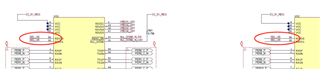
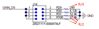
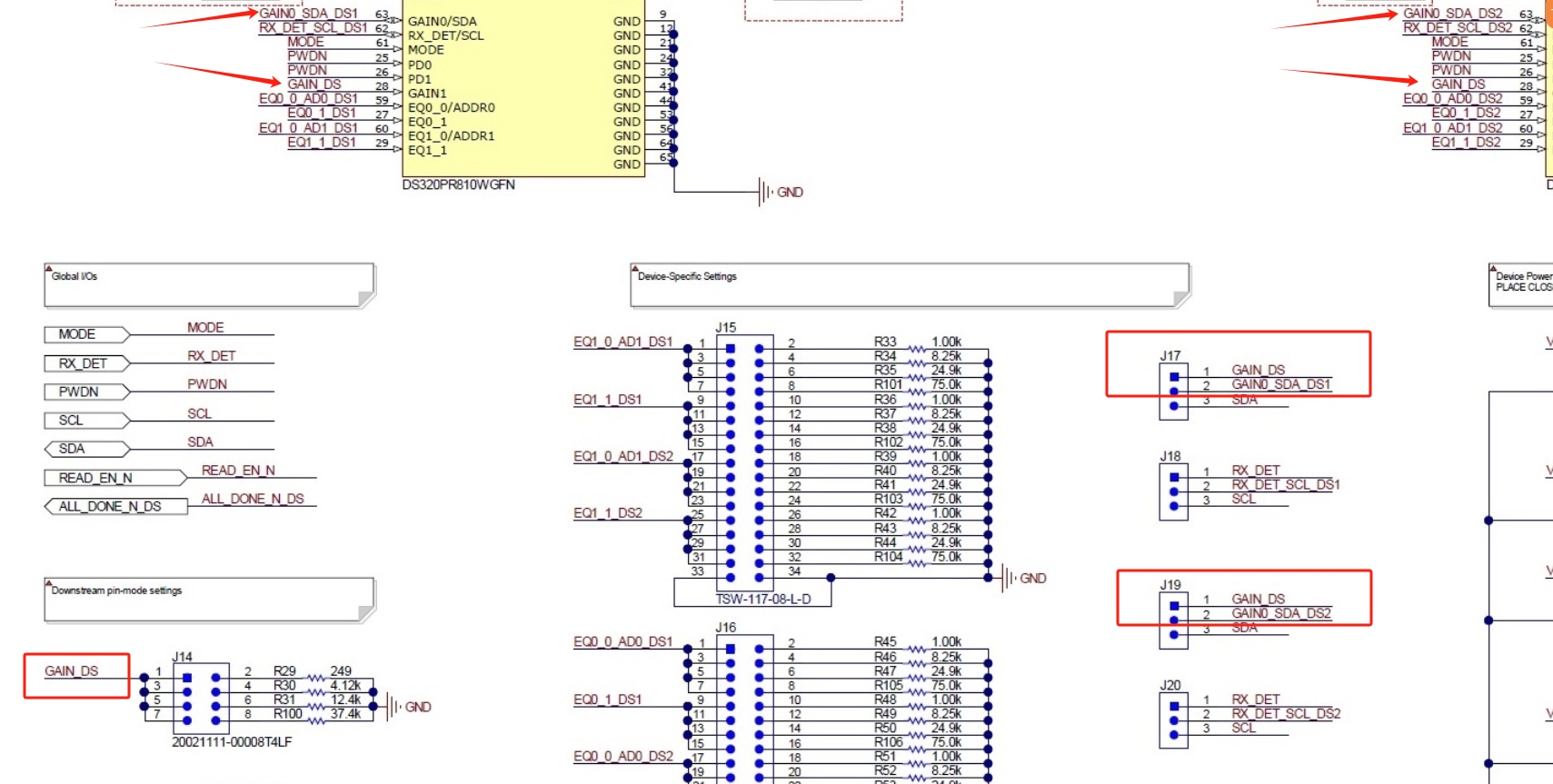
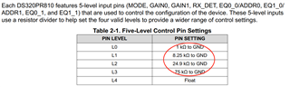
1. I saw the value of some strap resistors in the DS320PR810-RSC-EVM are not the same with those in the DS320PR810 datasheet. Could you please tell me why? 

2. The RSVD0/1 are connected together in the DS320PR810-RSC-EVM, but they are required to be left floating. Do they must be connected together? Why?

  • Hello Jacob,

    1. In the EVM, there are 4 different DS320PR810 redrivers. For certain configuration pins such as MODE, the EVM designers chose to link all of the pins to the same node, so that all devices could be configured to the same setting at once (it would be inconvenient for the EVM user to change four jumpers). Because of the internal circuit design of the strap pins, connecting the pins of four different devices to the same node is similar to having a parallel connection of four paths. So instead of using four separate strap resistors, it is simplified to one strap resistor with the value divided by 4.

    2. The RSVD0 and RSVD1 pins should be left floating on designs using DS320PR810.

    Best,
    David

  • Thank David.

    For the MODE and RX_DET in EVM design which are shared between 4 DS320PR810, the pull down resistor value is indeed R/4. Like below.

    But for the GAIN_US and GAIN_DS, which although are shared between 2 DS320PR810, totally 4 pins are connected to one resistor simultaneously(each redriver has GAIN0, GAIN1 two pins).

    The pull down resistors both have R/4 and R/2. I am confused about this.

  • Hi Jacob,

    Thank you for following up on this item.

    Please allow me to take a look at an EVM and compare to the schematic on Monday, as today is a holiday in the US.

    Best,
    David

  • Hi Jacob,

    I believe this may be a small mistake in the resistor selection.

    In either case, Level 0 of these pins biases to ~0 V, so practically speaking, either resistor value (249Ω or 500Ω) could work.

    Best,
    David

  • Thanks David.

    I think 249Ω is correct.  The resistor value which should be modified are R/2.

    4.12K should be 2.04K

    12.4K should be 6.19K

    37.4K should be 18.7K

    Am I right?

  • Hi Jacob,

    (redacted corrected below to avoid confusion)

    Best,
    David

  • Hi David,

    Yes,2x DS320PR810 devices share one GAIN_DS/GAIN_US. But each DS320PR810 has two GAIN pins(GAIN0 and GAIN1), then there will be 4 Pins share one GAIN_DS/GAIN_US. If so, the resistor value may be still required R/4.

    Or, GAIN0 of each DS320PR810 doesn't need to connect with GAIN_DS/GAIN_US?

  • Hi Jacob,

    Apologies - yes, you are correct that each GAIN_xx net drives two GAIN pins on each DS320PR810 device. R/4 would be sufficient if strapping 4 GAINx pins for this device.

    Best,
    David