Part Number: TCA8418
Tool/software:
Hi all,
We have a custom iM.X8MQ board and a keypad circuit connected to it, including TCA8418RTWR.
Configured Registers:
0x01 -> 0x19 (tca8418_keypad driver does so)
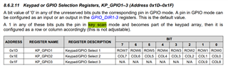
0x1D -> 0x0F (4 rows)
0x1E -> 0x0F (4 cols)
And I have been dealing with the datasheets and documents, currently I have some confusions.
1) "TCA8418 I 2C Controlled Keypad Scan IC With Integrated ESD Protection" page 37 has this statement below:
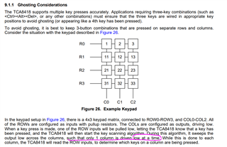
In the keypad setup in Figure 26, there is a 4x3 keypad matrix, connected to ROW0-ROW3, and COL0-COL2. All of the ROWs are configured as inputs with pullup resistors. The COLs are configured as outputs, driving low. When a key press is made, one of the ROW inputs will be pulled low, letting the TCA8418 know that a key has been pressed, and the TCA8418 will then start the key scanning algorithm. During this algorithm, It sweeps the output low across the columns, such that only 1 column is driven low at a time. While this is done to each column, the TCA8418 will read the ROW inputs, to determine which keys on a column are being pressed.
So, in the idle connection we have our ROWx pins HIGH, pulled-up internally and COLx pins LOW.
After pressing a key, a ROWx pin should be pulled LOW.
Then, the statement tells us the IC will execute a "sweep" the output low for the columns, but don't they have all LOW signals? What's the meaning of this? How could IC tell which button is pressed in ROWx?
2) ROWx is pulled-up in the idle scan connection. So, how pressing a button make a pull-down or a LOW signal happen there? I couldn't understand the ROWx-button-COLx relationship. Could anyone elaborate?
The current setup of ours works like below:
Pressing a keypad button doesn't change ROWx status, all rows stay HIGH.
COLx goes HIGH.
No scan occurs.
INT stays HIGH all the time.
3) Idk if it's related or indicating any error, GPIO_DAT_STAT1–3 (Address 0x14–0x16) has values of 0xFF, 0xFF and 0x03 and I cannot clear or rewrite them.
Thanks in advance,
Onur