Other Parts Discussed in Thread: TCA8418E
Tool/software:
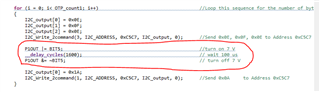
We want to program the TCA8424RHA by the I2C interface. we don't use the EVM board,
we just want a document to describe how to program this device for third party.
This thread has been locked.
If you have a related question, please click the "Ask a related question" button in the top right corner. The newly created question will be automatically linked to this question.
Hi Luke,
The firmware .zip file can be downloaded from the product page:
TCA8424 data sheet, product information and support | TI.com

This should include sample code header and .C files for reference using the MSP430.
The TCA8424 supports HID over the I2C bus.
The figures throughout the datasheet help to explain the frame formatting for reading and writing from/to the device:
Example:

Regards,
Tyler
Hi Tyler,
I have one more question, according to the code, when programming the OTP, the voltage in TEST pin would change from 1.8V to 7.0V repeatly.
could the voltage on this TEST pin always be 7.0V when programming the OTP.
Thanks a lot
Luke
Hi Luke,
This OTP creation app note might be helpful.
the code do give us much help. By the way, how to read the OTP data out after programming to verify. The code just read the data from address 0xA000, but it seem did not work for me.
What do you mean by didn't work?
You read from SRAM address 0xA000 and no data was given? What data did you write for address 0xA000?
Is the data reading 0x91?
I have one more question, according to the code, when programming the OTP, the voltage in TEST pin would change from 1.8V to 7.0V repeatly.
could the voltage on this TEST pin always be 7.0V when programming the OTP.
TEST pin can have input voltage of 7V when programming the OTP.
For normal usage of this device, this pin must be grounded.
Regads,
Tyler
Hi Luke,
Have you tried reading the OTP similar to the below figure?

I think it should be
Start bit,
I2C device address
Write
ACK
OTP address LSB
ACK
OTP address MSB
ACK
repeated start
I2C device address
read
ACK
data...
NACK
STop
I believe the OTP addresses have an hex "A" in the register address

Let me know if this works. Otherwise, the only way I would know for sure is using the EVM module to write and check the OTP through the GUI.
Regards,
Tyler
Hi Tyler,
Thanks, it works for reading the OTP, just need to set the address from 0xA000 which seems we could just read the RAM address after power the device.
Now the remaining question is that the code of EVM shows that during programming, the voltage on TEST pin seems would be turned on and off repeatedly,
it would be turned on for about 100us for each byte and then turned off before send 0x0A to address 0xC5C7.
I want to confirm could I set this TEST pin always be 7V when programming, as our hardware may not support to toggle so fast.
Hi Luke,
I would side with the EVM programming turning ON and OFF the test pin at 7V.
I believe this is part of the burn in process.
If you can't do 100us toggling speed, I assume that this device can support slower speeds for burn in. Toggling at several milliseconds should be okay. It will just make the overall OTP process slower.
Regards,
Tyler
Hi Tyler,
we check the EVM code and schematic, we found there's anther LDO that generate 1.8V also on TEST pin. And during programming, this LDO is always on, so when the 7V is off, actually 1.8V is still on the TEST pin.
But there's no information about this 1.8V in the datasheet, what is the function of this 1.8V. is this also a must?
As we need to program tens of thousands of this chip, and it is OTP, we could program one time for each chip, so we have to make everything clearly.
Hi Luke,
I understand the severity of programming the OTP since this occurs one time for each chip. TCA8418E is the alternative to this device, since TCA8424 is NRND.
we check the EVM code and schematic, we found there's anther LDO that generate 1.8V also on TEST pin. And during programming, this LDO is always on, so when the 7V is off, actually 1.8V is still on the TEST pin.
Was this 1.8V directly measured on the EVM? Which device part number generates the 1.8V?
Regards,
Tyler
Hi Tyler,
sorry reply late for the Labor DAY.
we don't have the EVM, so we did not measure it on the EVM. But according to the schematic, the device TPS77001DBV with it's application circuit generate 1.8V on the TEST pin.
And in the firmware code, this 1.8V is always on in the programming. And the protection diode CR1 protect this LDO when another high voltage 7V enabled on the TEST pin.
Hi Tyler,
You could just calculate the output voltage of TPS77001(about more than 2.3V) by its formula and the value of R8 and R9. And according the BOM of EVM, the CR1 is SD103CW-13-F, its forward voltage drop is about 600mv. So we get the voltage on TEST pin is more than 2.3V-0.6V =(1.7V -- 1.8V).
Hi Luke
In this case, I would side with the code following the toggling of 7V for burning in the OTP.
Also in the schematic:

TPS270 shows a 7V input voltage connected directly to the test pin.
I would assume that voltage at VTEST = 7V for burning in the OTP.
VTEST = GND for typical operation.
Regards,
Tyler
Hi Tyler,
I know for burning the OTP, VTEST is 7V. But besides the TPS270 connect to the TEST pin, the application circuit of TPS77001 also connect to TEST pin.
according to firmware code, The 7V is not always on. it is only turned on for 100us for burning 1 byte. and then turned off for send 0x0A to address 0xC5C7 and 0x0E 0X0F 0X0E to address 0xC5C7. So when the 7V is turned off, actually the voltage on the TEST pin is not 0V, it is about 1.8V from the TPS77001 circuit.
Hi Luke,
Is it possible to conduct burn in test with 7V and 1.8V toggling for each byte, and read back the OTP to see if the burn in test was successful? I would side with what the EVM shows in the schematic and go off those voltages.
This part is older and there is not much documentation on the process of the burn-in testing other than the EVM.
Regards,
Tyler