This thread has been locked.

If you have a related question, please click the "Ask a related question" button in the top right corner. The newly created question will be automatically linked to this question.

AM26LV32E: Question about AM26LV32EIPWR

Part Number: AM26LV32E
Other Parts Discussed in Thread: AM26LV32

Tool/software:

Hello:

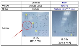
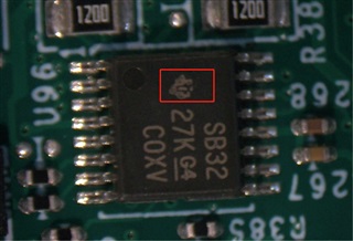
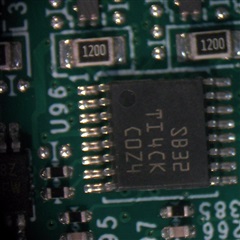
There is a TI material 18015 AM26LV32EIPWR. Currently, all products with TI logo on the silk screen can pass the test, but those batches without logo cannot pass the test.

Please confirm the difference between those with and without a logo.


The specific issues are as follows:

The previous products had logos on them, and there was no problem with the silk screen printing output status.

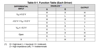
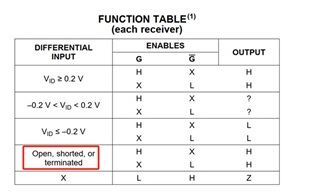
The current products do not come with logos, and the output status of this silk screen printing is incorrect. It should be high level, but in reality, some pins output low level.


From the PCN perspective, the modification of displaying two PCNs does not affect the functionality, but in actual testing by the customer, it was found that the chip with the ECAT logo has a high output without input.

But after testing six chips without logos consecutively, the outputs were all random. For example:

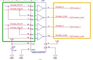
There are a total of 4 output pins, and the first chip may have pins 1, 2, and 3 high and pin 4 low. The second chip has pins 1, 2, and 4 high, and pin 3 low. This random method.

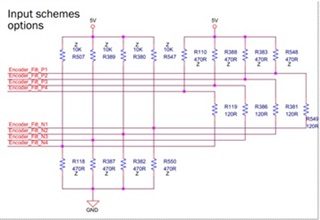
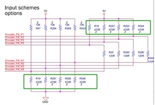
The customer speculates that there may have been changes in the internal pull-up circuit during the previous batch changes?

This ultimately led to the results of the test.

Please help confirm if there are any relevant changes, thank you.

  • The description in section 8.3.2 of the datasheet is somewhat misleading; the AM26LV32E has fail-safe only for open inputs, but not for shorted or terminated inputs. Please show the schematic; do you have termination resistors?

  • Hi Jimmy,

    I believe I am already working with the field team on this issue through email. Just to verify though, does the customer use 28k resistors on the inputs?

    I'm still trying to get a schematic but if this is a different customer, I may need to see the schematic like what Clemens suggested. 

    -Bobby

  • Hi Clemens & Bobby:

    Before input, there are TVS and common mode inductors, as well as 120 ohm terminal resistors, as shown in the following figure:


    (It should be noted that the above version is older, and the grounding wiring for L32 and L33, pins 1 and 4, are not actually available.)
    The issue we are currently experiencing during testing is with an open input circuit.
    But good products and bad products, all other circuits are the same, the only difference is the batch difference.
    All logos with the following image output a high level under open circuit conditions:
    But for chips without this logo, the output is random.


    Additionally, regarding the truth table in this chip datasheet, please refer to the following figure:


    From the graph, it can be seen that when there is an actual voltage input between ± 0.2V and the Open state, OUTPUT is different.
    In actual testing, we tested the open circuit condition. All chips with logos are as shown in the table above, and the OUTPUT is all H, so there is no problem.
    But the chip without logo does not match the picture above.
    Could you please explain your definitions for the two states of ± 0.2V and Open in the above figure?
    Does' Open 'mean input open circuit?

    In addition, Our client found another datasheet from 2008, but the condition description for the truth table is different. Please refer to the attachment for the 2008 datasheet.
    In the old datasheet, the description is as follows:


    As shown in the red box above, this is different from the latest description, which only states' Open '.
    May I ask if there have been any changes here? Is it possible that it is related to this current problem?

  • "Open" means that nothing is connected. But you have termination resistors.

    You need fail-safe resistors to get a differential bus voltage of at least ±0.2 V when the driver is idle. The schematic shows them, marked with "Z" (whatever that means).

    The datasheet changes were made in revision D (2020). I guess there was some confusion with the AM26LV32 (without -E), which does have full fail-safe inputs.

  • Hello Clemens:

    I still have a few points that I don't quite understand.
    1.Currently, chips with or without logos have different output performance, and I don't see a clear reason from TI yet.


    2. TI's response states that a fail safe resistor is required to obtain a voltage greater than 0.2V. This design is commonly referred to as a pull up resistor or a pull down resistor. Is that what it means?
    If so, we have reserved this for you, as shown in the picture we shared with you before:


    Please refer to the signal in the green box in the picture. This is the input of AM26, which is currently not soldered in the standard BOM. If soldered, the input will continue to have a voltage greater than 200mV, and we will not be able to perform disconnection detection.
    The reason why we have been asking you this question is because we need to perform disconnection detection, which is the four signals in the yellow box in the above picture.
    Under normal circumstances, pin3 and pin5 have opposite levels, while pin11 and pin13 have opposite levels.
    Previously, when using chips with logos, in the case of an open input, all 4 output levels were high, and our software would know that the input was open and report an error.
    But now without LOG chips, the output is random, which makes our function unusable.


    3. TI replied that we have 120 ohm terminal resistors, but in reality, we removed these terminal resistors and conducted tests. The AM26 output is still random.


    4. In the last sentence of TI's reply yesterday, it was mentioned whether the AM26 model comes with an E, which may cause confusion. Can you explain the difference between whether it comes with an E or not? We use chips with E. In addition, Ti mentioned full fail safe input. What does this completely fail safe input mean? Is it a function of this chip? Can you describe it in detail?

    Thanks!!!

  • 1. PCN# 20230814006.1 introduced a new die. Apparently, the behaviour for invalid input voltages is different; I'd guess that the new die has more hysteresis.

    2. Yes, you need to add these pull-up/-down resistors. Even with those resistors, disconnection detection is possible, because all resistors pull the P and N signals in the same direction, so all outputs will be high.

    4. I am not a TI employee. With "full fail-safe inputs", I mean inputs that output high when the pins are open, shorted, or terminated. The AM26LV32 does have full fail-safe inputs; the AM26LV32E does not.

  • Hello Clemens:

    Thank you for explaining the safety fault input function. If this safety fault input function (full fail safe inputs) is as described by you.
    The core issue now is that we have been using AM26LV32E and have been using models with "E". However, based on current testing, it has been found that for our chips with "E", all those with logos have safety fault input function, and all those without logos do not have this function.
    The latest ones do not come with logos and do not have this feature.
    Without this feature, we would not be able to conduct short-term testing, which is currently a problem for us because our product has this short-term testing function.

  • Jimmy,

    You should be able to ensure the output state of the device by adding the external pull up and pull down resistors on the inputs (the 470 ohm resistors). Are you still getting random outputs with those resistors populated?

    -Bobby

  • Hi Bobby:

    When adding an input pull-up resistor, the output is not random, but fixed.
    The key issue is that the 4-channel output is "high, low, high, low", which belongs to a state with an encoder input signal. In this way, we won't be able to perform disconnection detection.

  • In your schematic, all "P" signals are pulled up, and all "N" signals are pulled down. So when they are disconnected, all four outputs should be high. Does this not happen?