Other Parts Discussed in Thread: BQ25798, , TPS25751, TPD6S300
Tool/software:
Hi, Team
My customer use TPS25751D+BQ25798+TPD6S300A in one of their design.
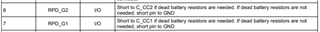
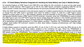
TPD6S300A mention that if RPD_G1/RPD_G2 short to GND, it means it support "dead battery resistors".
I think in TPD6S300A , the "dead battery resistors" you're talking about are the 5.1K ohm Rd CC resistors. The TPS25751D chip already has a "dead battery mode." When it's in this mode, the TPS25751D will put a 5.1K resistor to ground on the CC pins.
So, since the TPS25751D already does this, do I still need to connect RPD_G1/RPD_G2 of the TPD6S300A to C_CC1/C_CC2? Or should I connect RPD_G1/RPD_G2 to GND (ground)?
I'm worried that if I connect RPD_G1/RPD_G2 to C_CC1/C_CC2, then in dead battery mode, there will be two 5.1K resistors pulling down to ground: one from the TPS25751D and one from the TPD6S300A. Will this cause a problem?
In this situation, should I connect RPD_G1/RPD_G2 to C_CC1/C_CC2, or should I connect RPD_G1/RPD_G2 to GND?
Thanks.
G.W