This thread has been locked.

If you have a related question, please click the "Ask a related question" button in the top right corner. The newly created question will be automatically linked to this question.

THVD8000: Recommendation when selecting buck converter to tap power off of PLC bus

Part Number: THVD8000


Tool/software:

Hi,

I have a multi-node setup where each node will pull power off of the power line and power their MCU using a buck converter.

My Fset frequency is 500Khz and I am planning to use a buck converter that switches at 400kHz.

Will this cause issues to my communication? Will selecting buck converter with a higher switching frequency such as 1.1Mhz be a better choice?

Also, if I have long cable run and the voltage on the line varies due to dynamic loads of all the nodes, will that cause issues with communication?

  • Hi Yixing,

    So I wouldn't pick a buck converter with a switching frequency within tolerance range of the THVD8000's modulator - which is +/-25% so lowest modulation frequency is going to be 375KHz with a 500KHz setting. Also - while not directly stated in the datasheet the internal demodulator includes a bandpass filter to "select" the OOK data signal coming into the THVD8000 during receive mode and that bandpass filter has a very wide passband that generally expands past the +/-25% tolerance of the set frequency (it isn't directly spec'd so I don't have an exact "number" to give here - but just know that the demodulators passband will generally go past F_mod +/-25%). 

    The main reason being is that the THVD8000 is noise sensitive - for 500KHz you could possibly  only see a hysteresis between a logic 1 and a logic 0 of between 20 to 40mV and the injected noise from the buck converters input onto the shared bus may be mistaken for a logic low signal (logic low means that a pulse train was detected by the THVD8000) which could impact data integrity. 

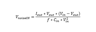
    You can look at your specific buck converter design you are using to estimate the noise - there are two main cases to look for for estimating the noise from the input of the buck. 

    Conditional Statement: 


    If the conditional statement is > 1 then the peak to peak noise on the input capacitor of the buck converter is as follows:

    Where if the conditional statement is < 1 then the peak to peak noise on the input capacitor of the buck converter is as follows:

    This will give you a magnitude of the switching noise on the input - and the fundamental frequency will be the switching frequency of the buck converter. 

    With that in mind - my main suggest is actually to keep the 400KHz switching frequency buck and increase the modulation frequency to at least 1MHz (which has the benefit of smaller coupling inductors between the power source/loads due to the higher modulation frequency) as well as ensuring that there is a relatively high amount of input capacitance - not only will that remove OOK noise from the input of the power supply at a higher level - but it will reduce the amount of noise injected back onto the shared bus. 

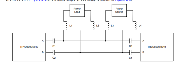
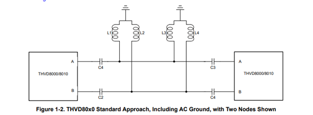
    For your second question - please see a simplified diagram of a THVD8000 application below:

    The power loads/power sources can be dynamic and if proper design protocol has been followed it shouldn't be a major issue. 

    Essentially when picking inductor and capacitors for the application it is important to keep the proper impedance levels so that the THVD8000 can properly drive the load. 

    It is assumed that the power source and power loads all include bulk capacitance - which they will for buck converters in the form of the input capacitor and assuming that a different DC source is providing the input power for the other buck converters on the lines I'd assume there would be bulk output capacitance on the main DC source. 

    The reason this is important is because the THVD8000 will now see everything beyond the inductors as "AC GND" 

    Will all bus loading from inductors and other THVD8000's considered the common mode impedance (which is one value used to signify both the A and B lines to GND impedance - this follows standard RS-485 which means the minimum is 375 ohms for terminated systems). 

    So as far as the THVD8000 is concerned there is no power source or power load - as the inductors connect to "gnd" (it isn't really ground - but to the THVD8000 it is). 

    Also since the main energy for the power line will be DC very little power signal will make it through the coupling capacitors (shown as C1 - C4 above). 

    The biggest concern is basically the switching noise for the buck - but as long as noise is minimized and you separate the switching frequency range from the OOK modulation frequency range it shouldn't be that big of an issue. Also since this is a noise sensitive devices - additional filtering on the communication nodes can include split terminations, filter caps on A and B to GND (no more than 100pF if used for best results - but start lower than 100pF - like around 50pF) can help increase performance. The biggest concern is you don't want the buck switching a similar speed to the OOK data because the THVD8000 could read the switching noise as a pulse train depending on noise magnitude. 

    I have also attached a component calculator to this thread that can speed up picking LC values - one note on the calculator - the equations do deviate from what is shown in datasheet - datasheet equations do not include loading from other THVD8000s - the calculator does. For smaller node counts you will get very similar results but as you start increasing number of nodes the loading from the other transceivers do matter.

     8308.THVD80x0_Design_Calculator.xlsx

    Please let me know if you have any other questions and I will see what I can do!

    Best,

    Parker Dodson

  • Thank you for the info!

    However, I do want to keep the modulation frequency at 500kHz so that I can maintain a longer wire run compared to the 1Mhz modulation frequency. I also do have a buck regulator that switches at 1.1Mhz frequency. Then this option, where I keep the 500kHz modulation and run the buck the buck switching frequency to 1.1Mhz would also be a viable solution, right?

    Also, I know that it's recommended to maintain a minimum line impedance of 54 Ohms so that the THVD8000 can drive the line to the correct 1.5V magnitude level and prevent wear and tear. Is there an absolute minimum of the line impedance where the THVD8000 can drive the line correctly and still maintain longevity?

    Thanks,

    Yixing

  • Hi Yixing,

    I am not sure how long your bus is - but you can still usually do 300m to 600m with 1MHz - we have tested the THVD8000 using 20-AWG UL2464 power cables and we have this table of estimated distances (the further closer to the max distance you get the worse the jitter gets):

    Regardless - if your buck converter is at 1.1MHz and the modulation frequency is at 500KHz that should be mostly okay - the coupling inductors along with a good sized input capacitance of the buck converter will help cut down on a lot of the noise - and 1.1MHz should be outside of the THVD8000 receivers passband. That being said I would implement a split termination on the end nodes of the bus (other nodes should be left unterminated - only the 2 ends should be terminated) 

    Where Rterm/2 = 60 ohms and Csplit would be sized according to  fc = 1/(2*pi*(RTerm/2)*CSplit)

    I'd select 625KHz for fc which gives us a Csplit value of appx. 4.2nF - this will help futher filter out any frequency above fmod +/- 25%. 

    In addition to the split terminations - I'd suggest a common mode choke on the communication nodes if possible to help cut down on any noise injected onto the bus. This may not be necessary - but if there is space in your system I'd at least include a footprint for it on the board so that in can be added if needed. 

    So on the cabling question - ideally the two end nodes of the bus are terminated with a DC impedance of 120 ohms - which gives a total load as seen by the driver of 60 ohms - which we can add +/-10% still and maintain above the 54 ohms. Ideally the cable has 120 ohm characteristic impedance so that the end nodes are impedance matched to the bus to mitigate reflections - it is assumed that the non-terminated nodes have very little deviation from main bus as this allows us to not need to terminate those nodes. 

    However - this device is a bit different due the applications it is used in - most power cable is not impedance controlled - meaning that most wiring meant to carry power doesn't control for impedance - there are a few exceptions I have seen but not many. This means that controlling for reflections is very hard to do in these applications that use the THVD8000. It ends up not being a huge issue most of the time because the 120 ohm resistor will mitigate some reflections - and the energy most likely to reflect is going to be higher frequency energy outside the THVD8000's receiver bandpass passband. 

    So in short - most power cable can be used - we have tested this device with standard RS-485 cable (which is twisted pair unshielded 120 ohm characteristic impedance), the 20-AWG UL2464 power cable, and generic off the shelf thermostat wiring that you can find in most hardware stores and we have found the device can communicate on all of the. In a perfect world it would be 120 ohm character tic impedance - however that isn't super practical with most power cabling. 

    As for the impedance seen by the driver - we generally only consider DC impedance for that specification - i.e. the cable just looks like a short circuit. When we say the minimum impedance of 54 ohms we mean through a resistive link. AC losses from the cables capacitance and any node capacitance should be considered as it can reduce max distance achieved - but as for the "impedance of the cable" - it has way more to do with signal integrity that actual drive strength. However as I have alluded to in this thread - the THVD80x0 devices are fairly robust and flexible devices as long as the base guidelines are followed. 

    Please let me know if you have any other questions!

    Best,

    Parker Dodson