This thread has been locked.

If you have a related question, please click the "Ask a related question" button in the top right corner. The newly created question will be automatically linked to this question.

THVD2450: Receiver mode - RO is drive low

Part Number: THVD2450

Tool/software:

Hey 

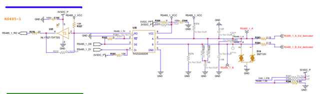
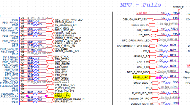
We are working with this RS485 transceiver .

We found that our MCU is stuck because of lot of bit that the transceiver transmitted to it 

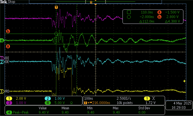
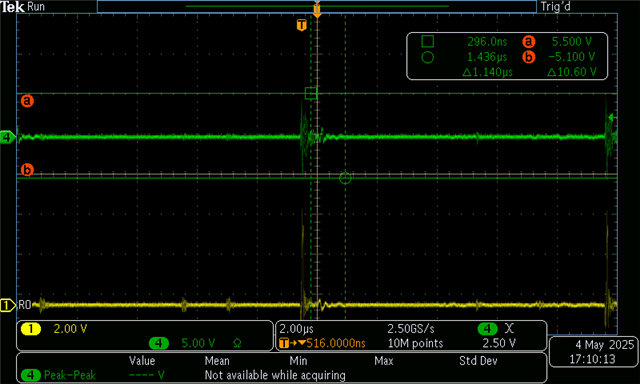
We are in pretty noisy environment and made some waveform picture and investigation.

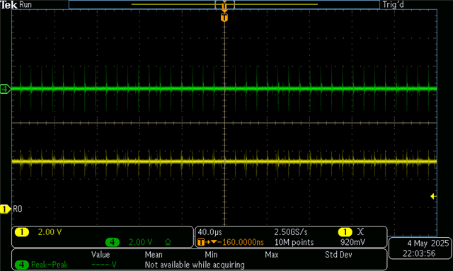
During our investigation we found that the RO is drive always drived low even if the Va-Vb voltage is above the -200mv.

you can scop picture as below :

i don't understand why RO is always drived low , can you help ?

Also we check the possibility to add cap for filter the noise from the AB ( A to GnD , B to Gnd and A to B) with value of 220pf , WDYTH ?

  • Hi Eytan,

    Thanks for reaching out about this issue you are experiencing. I have a couple of initial questions/comments:

    • Can you share a schematic so I can verify the device configuration?
      • Does the R output have a pulldown resistor (if you cannot share a schematic)? 
    • How long is R low for? Or does R stay permanently low?
    • How have you setup the enable pins DE and /RE? Are they tied together? For the receiver to function, please ensure /RE is at GND (since it has inverted logic). The noise on DE is the most concerning to me. The A/B lines are meant to handle noise as they are differential, but the transceiver will perform inconsistently when the enable pins experience that much noise.
    • How low does the voltage get on the DE pin? Looking at the voltage swing, it seems to hit -1V. Because this is outside the absolute maximum of the logic pins (-0.3V), there is a chance the enable pins could be damaged. However since this is in the nanosecond range, the device might still be ok. 

    Also we check the possibility to add cap for filter the noise from the AB ( A to GnD , B to Gnd and A to B) with value of 220pf , WDYTH ?

    You could certainly try this, but I doubt this would fix the issue. My current guess is that the enable pins are preventing the R pin from switching properly.

    Best,

    Ethan

  • Hey Ethan :) 

    thanks for the quick response 

    1. The schematic is as below 

    RO is with a PU of 10k 

    2. Its look that R is permanently low as you can see below 

    DE and RE are shorted together .

    the noise on RE/DE may be related to our measurement set-up , but we will try to check it more .

    its look that 3 caps of 220pf on the AB lines (A to G , B to G and A to B) fix it as you can see below example 

    So basically its look that there is not concern with the DE/RE pin , correct ?

    if this is the case , i still don't understand why we have RO low all the time without the additional caps

  • The receiver measures the differential input voltage. Please tell the oscilloscope to compute A−B. 

  • hi 

    the green waveform is a differential measurement Va - VB

  • Hi Eytan,

    Good call testing with those caps anyway. 

    How is your RS-485 bus configured? (i.e. what device is driving the bus signal and how many nodes are present)

    Your V_OD seems to be a pulse. Can you try outputting a slower square wave to the bus instead? 

    Best,

    Ethan