Part Number: TUSB8041EVM
Tool/software:
Dear TI Support,
I’m currently designing with the TUSB8041RGC and while analyzing the schematic of the TUSB8041RGC EVM (REV D), I noticed a mismatch regarding the crystal load capacitors.
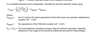
In the EVM design, C1 and C2 are each 18 pF.
However, the crystal used in the design has a load capacitance (CL) of 20 pF according to its datasheet.
When I apply the standard formula:
C1=C2=2×(CL−Cparasitic)C1 = C2 = 2 \times (CL - C_{parasitic})C1=C2=2×(CL−Cparasitic)
The result I get is 32 pF, assuming 4 pF of typical parasitic capacitance. That’s quite different from the 18 pF used in the EVM.
Can you help clarify:
-
Was a much higher parasitic capacitance assumed in this layout?
-
Is the 18 pF a mistake or intentional?
-
Should I really be using something like 32 pF in my design?
Thanks in advance for your clarification.