This thread has been locked.

If you have a related question, please click the "Ask a related question" button in the top right corner. The newly created question will be automatically linked to this question.

TCAN1472-Q1: The effect of SIC

Part Number: TCAN1472-Q1

Tool/software:

Dear Specialists,

My customer is confirmed with the effect of SIC and has a question.

I would be grateful if you could advise.

---Question

We replaced the CAN FD SIC transceiver "TCAN1472VDRQ1" used in our products with the CAN FD transceiver "TCAN1042HGVD" and checked the ringing waveform.

Could you please see attached PDF file.

Ringing_Check .pdf

As a result, the signal change time became shorter, but the ringing only seemed to be suppressed slightly.
(See pages 4-5 of the attached PDF)

In Figure 4-3 of the PDF document on the SIC of TI's TCAN1462, the ringing seems to be greatly suppressed.
(See pages 1-3 of the attached PDF)

Could you please let me know why the SIC effect of TCAN1472 is little ?
Is it due to differences in network configuration?
Are there any other possible factors?

---

I appreciate your great help in advance.

Best regards,

Shinichi

  • Hi Shinichi,

    Yes, this will mainly be due to differences in network configurations to  ensure worse case scenarios and observe a more significant effect of the SIC device, thanks. 

    Best Regards,

    Michael. 

  • Hi Michael,

    Thank you for your reply.

    I talked with the customer regarding your answer, they have an additional request.

    Could you please take care of it ?

    ---Customer's request---

    I would like to indicate to users the effectiveness of the TCAN1472V's CAN SIC.

    Could you please let us know the specific environment so that I can reproduce the worst-case conditions described in the application note.

    With the current information, I cannot understand which part of the configuration caused the change in the ringing suppression effect.

    ---

    I appreciate your great help and cooperation.

    Best regards,

    Shinichi

  • Hi Shinichi,

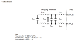
    Customer can use the specific network defined by CAN testing standard below or also create a non-ideal network configuration that introduces noise (example: using a cable with harness terminating at non-end nodes, long stubs, many connectors to several nodes on the CAN bus etc.) I.e., SIC used in  supporting non-ideal network topologies that typically introduce impedance mismatches observed as ringing, thanks.


     Best Regards,

    Michael.

  • Hi Michael,

    Thank you for your reply and sending test network.

    The diagram is unclear and the text is unreadable.

    In particular, the text on the component constants is unreadable.

    Could you please send a clear diagram.

    Could you please also tell me the component constants used when measuring the ringing waveform of the SLLA581.

    Are they the LCR constants shown in the diagram above?

    I appreciate your great help and cooperation.

    Best regards,

    Shinichi

  • Hi Shinichi,

    The image specifies the load as Csic 220 pF, Lsic 3 uH and Rsic 60 ohms. The components are the same as the ringing network (specified by CiA 601-4) mentioned in the app note, thanks.

    Best Regards,

    Michael.

  • Hi Michael,

    Thank you for your reply.

    I shared the information with the customer.

    When the customer has an additional question, I consult you again.

    I appreciate your great help and cooperation.

    Best regards,

    Shinichi