This thread has been locked.

If you have a related question, please click the "Ask a related question" button in the top right corner. The newly created question will be automatically linked to this question.

THVD1406: High supply current

Part Number: THVD1406

Tool/software:

I am working on a design with the THVD1406 and I dont understand some behavior.

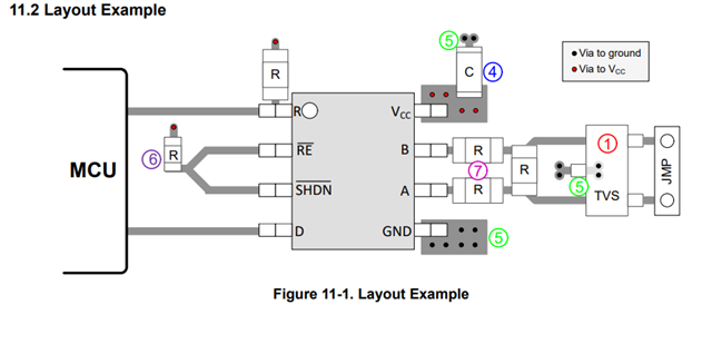
I did reproduce the datasheetfor my design with auto-direction

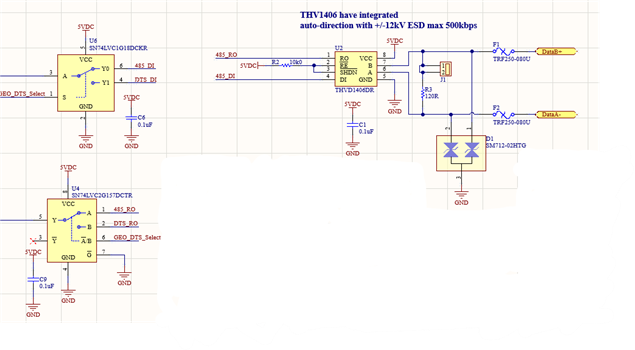
When I power the the circuit, I see a 40mA from my supply.

I did pull to ground the two select pins and the A pin going to 485DI. Those lines were not floating.

If I cut the 485 RO line, thats doesnt change the current

If I remove the R2 pull-up, that doesnt change the current

If I cut the line 485_DI, the current is going to a normal level for my circuit(10-12mA)

The DI pins is linked to the output of a 74lvc1G18DC(2:1 mux) with a supply at the same level(5V)

Measuring the voltage on DI input pin, I see 4VDC.It is suppose to be an input with high impedance?

The circuit is working, but it looks like something is wrong looking at the values.

Can you help me with that?

Also, why do you put a 10k on the RO pins in some schematics and not on other?

Thanks

Daniel Pelletier

  • Hi Daniel,

    When the device is actively driving the RS485 line, I would expect atleast around 25mA if the jumper J1 is shorted together. (3VoD of A-B voltage divided by 120 ohms). I would recommend shorting the Shutdown# pin to GND and verifying the current changes or not. 

    Are you able to probe the DI pin with a scope probe?

    You're correct. The DI pin is expected to be high impedance. This is making suspect the current may be coming from the DI trace/net some how. I would suggest desoldering the MUX and then connect DI to Vcc and GND with a resistor to see if the current changes.

    -Bobby

  • Hi Bobby

    The device is tested is passive mode, with no communication and nothing connected on the rs-485 output.

    If I short the shutdown pin to gnd, I have 10.13 mA feeding my whole circuit(It is normal for 6 other ttl circuit)

    I have cut the trace between the mux and the THVD1406

    If I put the shutdown and Re pin to VCC, I have the following : 

    DI floating : 10,85 mA(0.72mA for the THVD1406)

    DI to VCC : 10,85 mA(same)

    DI to gnd : 46.87mA (36.74mA for the THVD1406)

    If I left the DI pin floating, and measure it with the scope, I see 3.95V flat line

    I see sometimes voltage on floating input pins, but they normally dont draw much current when they are tied to vcc or gnd.

    I got the same behavior from three prototypes.

    I dont know what I am missing here.

    Any ideas, or other tests?

    Thanks

    Daniel Pelletier

  • If I put the shutdown and Re pin to VCC, I have the following : 

    DI floating : 10,85 mA(0.72mA for the THVD1406)

    DI to VCC : 10,85 mA(same)

    DI to gnd : 46.87mA (36.74mA for the THVD1406)

    With shutdown tied to Vcc the driver is active. So when DI is pulled to GND it indicates one of 3 things. You have a short from Vcc on the DI pin, there is a short on the A/B pins, there is a short on R out. I think we can rule out the last one based on the original post stating cutting Ro.

    If you tie Shutdown to GND then the driver is disabled. So if you still see high current when the DI pin is held to GND then the short is coming from the DI pin.

    If that is the case, I would suggest checking the soldering or maybe resoldering a new unit on U2. The DI pin itself is a CMOS input so the only current that is supplies would be a very weak leakage current probably sub nA. 

    You could also try to measure the resistance between the DI net and Vcc. 

    When you see the 4V on DI, also check the Vcc rail. It could be drooping due to the large current and generating the 4V output. 

    Measuring the voltage on DI input pin, I see 4VDC.It is suppose to be an input with high impedance?

    If you have the pin tied to 5V then you should see 5V. It should not be 4V as it is a high impedance CMOS input. 

    -Bobby

  • I have solved my case

    Everything works as supposed, I'm just not used to this autodirection circuit.

    If I remove the 120 ohms, the current stay low, so the current mostly goes to the load.

    The voltage bias that is see on the D input is probably normal and does not need attention.

    When the Input D input is low, the output driver is conducting to the 120ohms load.

    When the D input is high, the output driver is conductiong for only a small time and then goes high impedence. 

    On circuit with no auto-direction feature, you see the same current when the output is positive or negative, but on this one its not the case.

    Thanks for your help, I've needed a little push to go further.

    Daniel Pelletier