This thread has been locked.

If you have a related question, please click the "Ask a related question" button in the top right corner. The newly created question will be automatically linked to this question.

DP83TG720R-Q1: DP83TG720R-Q1

Part Number: DP83TG720R-Q1

Tool/software:

Hello Expert,

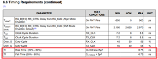
 Why the simulation shows good(0.7ns) on the rise time and fall time at 3.3V VDDIO, but the real measurement shows 1.62ns? the register confirmed in IC is default value of cfg_mac_rx_impedancede[9-5]: 01000b = Default mode (rgmii tr/tf compliant, max tr/tf=750ps)

May I know why? 

 dp83tg720r.ibs

  • Hi Jing,

    There are a few possible reasons:

    • There could be factors in the simulation environment that differ from real life, such as the S-parameters of the channel models
    • The measurement probe could be adding capacitance that increases the observed rise/fall time in the measurement, compared to the normal operational case

    I see you have made another E2E thread today that seems to also be related to the rise/fall time evaluation of the DP83TG720. Since there appear to be some technical queries there, I will focus on that one before returning to this case.

    Best,

    Evan Su

  • Hi Jing,

    Since I am told that the other thread has been resolved, I will return to this case:

    • Register 0x456 controls the slew rate/rise-fall time of the RGMII pins by adjusting the internal series resistance of the pin. If the register readback is now working correctly, it should be possible to check that 0x456[9:5] has the expected default value.
    • It is understood that the actual rise-fall time is a function of both resistance and capacitance. Higher capacitance = greater RC time constant = longer rise/fall times.

        • From the datasheet, we see that the 750 ps = 0.75 ns maximum rise/fall was characterized at a line/trace capacitance of 5 pF.
    • The observed 1.62 ns rise/fall time could be a result of the line capacitance for the measurement being higher than 5 pF. We recommend investigating the capacitance of the test setup in several places:
      • The line capacitance at the place that the RGMII signals are sampled
      • The capacitance of the probes used to measure the signal

    The DP83TG720 RGMII output pins have ~2-4 pF internal capacitance that likely will be included during a line capacitance measurement, but it should still be possible to tell if the observation is significantly higher than expected.

    Best,

    Evan Su