This thread has been locked.

If you have a related question, please click the "Ask a related question" button in the top right corner. The newly created question will be automatically linked to this question.

DP83822IF: The link status of DP83822IF 100 base-fx has always been 0

Part Number: DP83822IF
Other Parts Discussed in Thread: AM2634, , DP83822I, DP83822EVM, DP83869

Tool/software:

Hello, expert. I am using DP83822IF 100 BASE-FX to connect to the switch and finally connect to the computer. Between DP83822IF and the switch, two 155M SFP 1310nm 20km SM/LC modules are used to connect with two LC optical fibers. And the SD pin of the SFP module was connected to LED_1 / GPIO1 of DP83822. Now the loopback test between MCU AM2634 and PHY can be completed without errors. Meanwhile, when I plug or unplug any optical fiber, Both the link LED of the switch and the LED_0 of DP83822 can correctly indicate the disconnection and connection of the link.
However, when I run the APP program, the program shows that the link status of Bit 2 in Register 0x0001 is always 0, causing the program to be unable to establish a connection all the time. Where might the problem be?

  • Hi, 

    Now the loopback test between MCU AM2634 and PHY can be completed without errors.

    What loopback test has been done? Have you done the digital loopback test?

    causing the program to be unable to establish a connection all the time

    Do you mean the connection gets dropped some time according to the program?

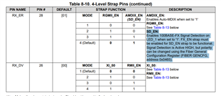
    Also, is RX_ER pin strapped so that signal detect is enabled?

     
    Could you share us the register dump from 0x00 to 0x1F and the schematic so we can better look into this problem?

    Best,
    J

  • Thank you for your patient reply. ① The loopback Test I used was the one that comes with the Layer 2 CPSW Test program. The specific code should be at the bottom layer and I haven't studied it myself. I didn't specifically conduct digital loopback tests. The RX_ER pin uses the default mode 4. My startup configuration is: COL=MODE3, LED_0=MODE4, LED_1=MODE4. The rest are all in the default state. The connection does not break from time to time. The bit2 register 0x01 is always 0, so it should be that the connection has never been established. However, LED0 can light up when I insert the optical fiber and go out when I pull it out. ③ The DP83822+ copper cable I used before could operate normally, but the SFP fiber I changed the starting resistor and added according to the manual couldn't work properly. ④ My PHY registers are as follows. Thank you.

    Image loading done, switching to application ...
    ==========================
    Layer 2 CPSW Test
    ==========================

    Init all peripheral clocks
    ----------------------------------------------

    Create RX tasks
    ----------------------------------------------
    cpsw-3g: Create RX task

    Open all peripherals
    ----------------------------------------------
    cpsw-3g: Open enet
    EnetAppUtils_reduceCoreMacAllocation: Reduced Mac Address Allocation for CoreId:0 From 4 To 2

    Init all configs
    ----------------------------------------------
    cpsw-3g: init config
    Link Status Changed. PHY: 0x1, state: up
    Open MAC port 1
    EnetPhy_bindDriver: PHY 1: OUI:080028 Model:24 Ver:00 <-> 'dp83822' : OK

    PHY 1 is alive

    Attach core id 0 on all peripherals
    ----------------------------------------------
    cpsw-3g: Attach core
    cpsw-3g: Open DMA
    initQs() txFreePktInfoQ initialized with 16 pkts
    cpsw-3g: Waiting for link up...
    PHY 1: *0 = 0x3100
    PHY 1: *1 = 0x7849
    PHY 1: *2 = 0x2000
    PHY 1: *3 = 0xa240
    PHY 1: *4 = 0x181
    PHY 1: *5 = 0x0
    PHY 1: *6 = 0x4
    PHY 1: *7 = 0x2001
    PHY 1: *8 = 0x0
    PHY 1: *9 = 0x0
    PHY 1: *a = 0x4100
    PHY 1: *b = 0x1000
    PHY 1: *c = 0x0
    PHY 1: *d = 0x401f
    PHY 1: *e = 0x0
    PHY 1: *f = 0x0
    PHY 1: *10 = 0x4
    PHY 1: *11 = 0x108
    PHY 1: *12 = 0x0
    PHY 1: *13 = 0x0
    PHY 1: *14 = 0x0
    PHY 1: *15 = 0x0
    PHY 1: *16 = 0x100
    PHY 1: *17 = 0x41
    PHY 1: *18 = 0x400
    PHY 1: *19 = 0x8021
    PHY 1: *1a = 0x0
    PHY 1: *1b = 0x7d
    PHY 1: *1c = 0x5ee
    PHY 1: *1d = 0x0
    PHY 1: *1e = 0x2
    PHY 1: *1f = 0x0

  • Hi,
    I will review more carefully on this and get back to you Monday CDT. Thank you.

    Best,
    J

  • Hi, 
    Could you share us your schematic? If not, what is your setup?
    Could you verify that SD signal on the link partner is active high? If not, you will have to adjust the SD pin to be active low on the PHY side by writing 1 to bit 0 of the register 0x0465. 

    Please let me know. 

    Best,
    J

  • ① Do you have an available email? I will send the schematic diagram to you
    ② Yes, I've written 1 to 0x0465. As I said before, the LED is already correctly showing if the fiber is inserted.

  • Hi, 
    You can private message me. Please accept my friend request. 

  • Hi, 
    I reviewed the schematic and I have some comments:
    1. 
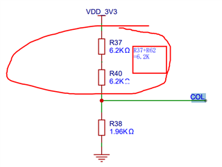
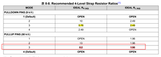
    I noticed that COL is meant to be strapped to mode 3, but it seems like this is not being strapped to the correct mode. Could this be changed to pull up to 6.2k?
    2. Could you put CRS into mode 4 instead of mode 2?
    3. 
    Is SD pin connected to this? If so, could this be disconnected since SD pin will not function as LED1 in fiber mode?

    How many PHYs are having this issue and how many boards are having this issue?
    We've had customers whose SFP cage was damaged that no link was present even when the LED was on. 

    If it is just one PHY, could you do a ABA swap on the PHY and the SFP cage and see if there's any improvement?

    Please let me know. 

    Best,
    J

  • COL is strapped to mode 3, because As I mentioned, R37+R40=6.2K,R38=1.96K

    ②I want to use 100 base-Fx, and PHY_ADD=1, so I need COL to use mode3

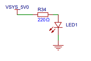
    ③SD pin is not connected to this, this is just a power indicator, this LED1 is the device name, not the network name. The LED1 of 822 is connected to the LOS pin of the SFP

    ④Currently in the sample stage, only one board is used for debugging functions.

    Best,

  • Hi, 
    1, 2, 3) Okay sounds good. 
    4) I'd suggest to check both the PHY and the SFP cage still. Because LED linking is decoupled from the link status register we have to check if it is a non-PHY issue or PHY issue. 

    Please let me know. 

    Best,
    J

  • Hi, how to check both the PHY and the SFP cage,The circuit is as shown in the picture, and I soldered them again, the problem is still the same.

  • Hi, 

    Could you do a ABA swap on the PHY and the cage? If either of them are broken, swapping them out should the fix the issue. If that does not solve the issue, please let me know. 

    Best,
    J

  • Hello, we are looking for the problem of PCB layout.
    ① Can you provide the PCB file of "DP83822EVM DP83822I 10-Mbps & 100-Mbps Ethernet PHY evaluation module" as our reference?
    ② There is only 100BASE-FX Waveform in the data sheet of DP83822. Could you please provide the waveforms of TX+, TX-, RX+ and RX-to-ground of PHY side and SFP side under connected and unconnected states? For example, "Application Note
    DP8382x IEEE 802.3u Compliance and Debug "is for 100 base-tx

  • Hi, 
    Please check the private message for the EVM board file. 

    ② There is only 100BASE-FX Waveform in the data sheet of DP83822. Could you please provide the waveforms of TX+, TX-, RX+ and RX-to-ground of PHY side and SFP side under connected and unconnected states? For example, "Application Note
    DP8382x IEEE 802.3u Compliance and Debug "is for 100 base-tx

    We do not have this data at the moment, and will take some time to collect the waveform. I still suggest to do ABA swap to see if the PHY or the cage fails if you are seeing valid fiber signal. 

    Best,
    J

  • The problem has been solved.

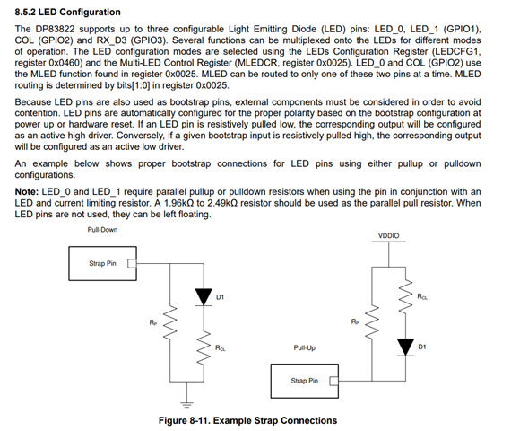
  • Hello, I have one last question about COL pin. Because I need to configure FX_EN=1 and PHY_AD0=1, I need to configure COL=MODE3, that is, RH=6.2k and RL=1.96K. After starting, I want to use it as a GPIO and drive the LED. May I ask how I should connect this LED without affecting the start of MODE3, whether it should be pulled up or down, and what should be the value of the pull resistance?

    thank you~

    Best,
    yc

  • Hi yc, 

    Good to know that you solved the problem. What was the cause?

    Regarding your question, please follow the same recommendation as below:


    Best,
    J

  • Thanks for the reply, the above figure is the reference of 2 level  strap, but COL pin is 4 level strap, but we have found the appropriate value through calculation and trial.
    Regarding the previous issue, it is due to the fact that AM2634 needs to be configured in software to use force mode because fiber does not support negotiation.
    While debugging I found a new problem, you can test it, it is Table 8-43. 0x001F PHY Reset Control Register (PHYRCR), bit 15 Software Reset, its description is: "This bit is self cleared and has the same effect as Hardware reset pin", but our test did not, our test results showed that he was able to reset the register, also able to reset the connection, However, the Strap cannot be loaded according to the external resistance, and can only be reloaded through the external RST pin.
    Much like DP83869, The description of DP83869 reads :"During software resets, the strap options are internally reloaded from the values sampled at power up or hard reset." and"Software Reset This will reset the PHY and return registers to their default values. Registers controlled via strap pins will return back to their last strapped values"

    Therefore, please help to confirm whether it is a document error.

    thank you~

    Best,
    yc

  • Hi yc, 

    Thank you for reply and I apologize for the confusion. Good to hear that you found an appropriate value through calculation and trial. 

    Regarding the soft reset, I again apologize for the confusion and straps are only sampled via hardware reset. We are currently in the process of revising this datasheet and this will be reflected in the next revision of the datasheet. 

    Best,
    J

  • It doesn't matter. All the problems have been solved now. Thank you for your patient support. We are also looking forward to the document update